Cisco 6500 VSS Configuration

It’s an old draft from 2010. Recently I was designing a network which VSS was on the topics, so it reminded me of the draft.

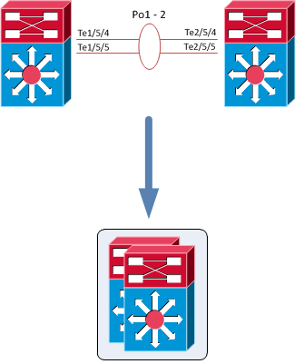
The Cisco Catalyst 6500 Series Virtual Switching System (VSS) allows the clustering of two chassis together into a single, logical entity. This technology allows for enhancements in all areas of network design, including high availability, scalability, management, and maintenance.

The Virtual Switching System is created by converting two standalone Catalyst 6500 systems to a Virtual Switching System. The conversion is a one-time process that requires a few simple configuration steps and a system reload. Once the individual chassis reload, they are converted into the Virtual Switching System.

All control plane functions are centrally managed by the active supervisor engine of the active virtual switch chassis, including:

  • Management(Simple Network Management Protocol [SNMP], Telnet, Secure Shell [SSH] Protocol, etc.)
  • Layer 2 Protocols (bridge protocol data units [BPDUs], protocol data units [PDUs], Link Aggregation Control
    Protocol [LACP], etc.)
  • Layer 3Protocols (routing protocols, etc.)
  • Software data path

The requirements to convert the 6500 into a Virtual Switching System are:

  • The VSS requires Supervisor Engine 720 with 10-GigabitEthernet ports. You must use either two VS-S720-10G-3C or two VS-S720-10G-3CXL supervisor engine modules.
  • The VSS requires 67xx seriesswitching modules.
  • The VSLEtherChannel supports only 10-Gigabit Ethernet ports.

Continue reading “Cisco 6500 VSS Configuration”

Share this!

IPX Vol.1 Switching Notes

Downstream switches inherit timers from the root (of each VLAN)

  • BPDUgurad blocks incoming BPDUs.
  • BPDUfilter blocks outgoing BPDUs.
  • bpdufilter default and bpduguard default work in conjunction with portfast default.
  • spanning-tree guard loop  is similar to UDLD, but users STP BPDU keepalive.
show spanning-tree mst [detail]
In MST, load-balancing with cost/port-priority is the same as CST, PVST.
interface f0/0
spanning-tree mst 1 cost 1
spanning-tree mst 2 port-p 0

All switches in the L2 transit path should know about the RSPAN remote-vlan, and the interconnections should be trunk. Remember to remove pruning for RSPAN VLAN from trunks.

IPphone tags voice traffic with CoS 5.

switchport voice vlan dot1p instructs the IP-phone to apply VLAN0 and CoS 5, so both Voice & Data share the same VLAN.

switchport voice vlan  automatically applies portfast.

mls qos trust device ciscoipphone means only trust CoS if received from IP-phone which is detected by CDP.

Fallback Bridging is the concept of bridging non-routed protocols between SVIs or native L3 router interfaces on switches. Similar to CBR and IRB on routers.

bridge 1 protocol vlan-bridge
interface f0/1
 bridge 1
  • PVLAN requires Transparent VTP mode.
  • Whenever a task asks us to optimize a switch for memory or routing, it means “sdm prefer routing“
  • Macros do not accept “interface range”!
  • When filtering traffic using mac-access-list remember to allow Spanning-tree and ARP stuff!

HSRP

  • standby use-bia  : not using the vMAC
  • standby version 2  : Uses 224.0.0.102 for inter-router communications instead of 224.0.0.2
standby 1 ip 150.100.220.1
standby 1 priority  : default is 100
standby 1  : not default
standby 1 track 1 decrement  // same as  standby 1 track Serial0/1/0 20

Remember to add static arp for hosts when filtering ARP in LAB exam. (show arp)

Share this!

Private VLAN

  • Members of an isolated VLAN can only communicate with the promiscuous ports mapped
  • Members of a community VLAN can communicate with members of the same community and the promiscuous ports.

A two-way community acts like a regular community but has the additional aspect of allowing access control lists to check traffic going to and from (two ways) the VLAN and provides enhanced security within a private VLAN.

To configure PVLAN, VTP should be in transparent mode.

  1. Create primary private-vlan
  2. Create isolated/community VLAN
  3. Associating isolated/community VLANs to primary
  4. Configure spanning-tree mode and associating ports to PVLANs
  5. Mapping PVLANs under the primary VLAN interface
  6. To verify: show interface [primary PVLAN] private-vlan mapping

IPExpert, Vol.1, 2.28

You must configure VTP to transparent mode before you can create a private VLAN.
Private VLANs are configured in the context of a single switch and cannot have members on other switches. Private VLANs also carry TLVs that are not known to all types of Cisco switches.

Configuration

SWITCH(config)# vlan primary_number
SWITCH(vlan-config)# private-vlan primary
SWITCH(config)# vlan secondary_number
SWITCH(vlan-config)# private-vlan [isolated | community]
SWITCH(config)# vlan primary_number
SWITCH(vlan-config)# private-vlan association secondary_number_list [add secondary_number_list]
SWITCH(config)# interface type mod/port
SWITCH(config-if)# switchport
SWITCH(config-if)# switchport mode private-vlan host
SWITCH(config-if)# switchport mode private-vlan host-association primary_number secondary_number
SWITCH(config)# interface type mod/port
SWITCH(config-if)# switchport
SWITCH(config-if)# switchport mode private-vlan promiscuous
SWITCH(config-if)# switchport mode private-vlan mapping primary_number secondary_number
SWITCH(config)# interface primary_number
SWITCH(config-if)# ip address address mask
SWITCH(config-if)# private-vlan mapping primary_number secondary_number
show vlan private-vlan type
show interface private-vlan mapping
show interface type mod/port switchport
Share this!

Switching Misc. 1

To authenticate 802.1x clients:
SW1(config)# dot1x system-auth-control
SW1(config)# aaa new-model
SW1(config)# aaa authentication dot1x default group radius
SW1(config)# radius-server host 150.100.220.100 key ipexpert
  • When a PC doesn’t support EAP, it can be placed in a guest-vlan:
    dot1x guest-vlan 200
  • When the authentication is failed:
    dot1x auth-fail vlan 100

Port-security table won’t survive a reload unless using “sticky” parameter.


switchport protected: The ports cannot communicate even with other ports in the same VLAN


Assign a static switching table entry
SW1(config)# mac-address-table {dynamic | static | secure} mac-addr {vlan vlan-id} {interface int1 [int2 … int15] [protocol {ip | ipx | assigned}]

If the destination port is a trunk, you must also specify the destination VLAN number vlan-id.

Set the switching table aging time:
SW1(config)# mac-address-table aging-time seconds [vlan vlan-id]

For VLAN number vlan-id (2 to 1001), entries are aged out of the switching table after seconds (0, 10 to 1,000,000 seconds; default 300 seconds). A value of 0 disables the aging process. The VLAN number is optional. If not specified, the aging time is modified for all VLANs.

Optimize the port as a connection to a single host
SW1(config-if)# switchport host

Several options are set for the port: STP PortFast is enabled, trunk mode is disabledEtherChannel is disabled, and no dot1q trunking is allowed.

Share this!

VTP

CDP v2 advertises VTP domain too. To disable this, no cdp  advertise-v2

VTP version can’t be changed on Client mode.

VTP Pruning is only implemented on VTP Server nodes.

VTP Pruning eligible-list is configured on TRUNK interfaces (switchport trunk pruning … )

VLANs which are not mentioned in the pruning eligible-list, will be never pruned.

VTP pruning can be only modified in server mode.

VTP pruning is propagated to clients too.

VTP mode can’t be server when existing VLANs exists.

Version-dependent transparent mode

In VTP version 1, a VTP transparent switch inspects VTP messages for the domain name and version and forwards a message only if the version and domain name match. Because only one domain is supported

in the Supervisor engine software, VTP version 2 forwards VTP messages in transparent mode without checking the version.

Share this!