
It’s an old draft from 2010. Recently I was designing a network which VSS was on the topics, so it reminded me of the draft.
The Cisco Catalyst 6500 Series Virtual Switching System (VSS) allows the clustering of two chassis together into a single, logical entity. This technology allows for enhancements in all areas of network design, including high availability, scalability, management, and maintenance.
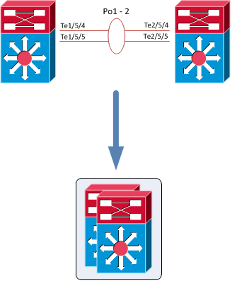
The Virtual Switching System is created by converting two standalone Catalyst 6500 systems to a Virtual Switching System. The conversion is a one-time process that requires a few simple configuration steps and a system reload. Once the individual chassis reload, they are converted into the Virtual Switching System.
All control plane functions are centrally managed by the active supervisor engine of the active virtual switch chassis, including:
- Management(Simple Network Management Protocol [SNMP], Telnet, Secure Shell [SSH] Protocol, etc.)
- Layer 2 Protocols (bridge protocol data units [BPDUs], protocol data units [PDUs], Link Aggregation Control
Protocol [LACP], etc.) - Layer 3Protocols (routing protocols, etc.)
- Software data path
The requirements to convert the 6500 into a Virtual Switching System are:
- The VSS requires Supervisor Engine 720 with 10-GigabitEthernet ports. You must use either two VS-S720-10G-3C or two VS-S720-10G-3CXL supervisor engine modules.
- The VSS requires 67xx seriesswitching modules.
- The VSLEtherChannel supports only 10-Gigabit Ethernet ports.
To convert two standalone chassis into a VSS, perform the following activities:
- Configure each chassis as a VSS
- Convert to a VSS
- Configure the dual-active detection (optional)
- Configure the switch priority (optional)
- Configure each chassis as a VSS
Define a switch virtual domain ID to identify the VSS. The ID must be the same on each 6500; in this example the ID ‘100’ is used:
1CISCO-A(config)#switch virtual domain 100
Domain ID 100 config will take effect only after the exec command switch convert mode virtual' is issued

1CISCO-A(config-vs-domain)#switch 1
1CISCO-B(config)#switch virtual domain 100
Domain ID 100 config will take effect only after the exec command switch convert mode virtual' is issued

1CISCO-B(config-vs-domain)#switch 2
Configure the VSL port channel and member ports:
The Virtual Switch Link (VSL), like the VPC peer-link in VPC, is clearly a vital part of the VSS. It provides the signaling path used for synchronizing the two supervisor engines’ control planes, as well as providing the data path for any user data traffic needing to pass between the two chassis.
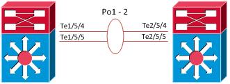

Choose unique port-channel IDs for each chassis to form the VSL and configure them with the corresponding switch ID:
1CISCO-A(config)#interface port-channel 1
1CISCO-A(config-if)#switch virtual link 1
1CISCO-A(config-if)#no shut
1CISCO-A(config-if)#exit
1CISCO-A(config)#interface range tenGigabitEthernet 5/4 -5
1CISCO-A(config-if-range)#channel-group 1 mode on
1CISCO-A(config-if-range)#no shutdown
1CISCO-B(config)#interface port-channel 2
1CISCO-B(config-if)#switch virtual link 2
1CISCO-B(config-if)#no shut
1CISCO-B(config-if)#exit
1CISCO-B(config)#interface range tenGigabitEthernet 5/4 -5
1CISCO-B(config-if-range)#channel-group 2 mode on
1CISCO-B(config-if-range)#no shutdown
- Convert to a VSS
Convert both switches to virtual switch mode. During these phases:
- The running configuration of the individual switch is converted into a three-level virtual switch interface notation. Two-level interface configurations (such as 10 GigabitEthernet 5/4) are converted into three-level interfaces (such as 10 GigabitEthernet 1/5/4 in Switch 1 and 10 GigabitEthernet 2/5/4 in Switch 2) like in a stack.
- The startup configuration is updated with the three-number notation.
- A copy of the original startup configuration converted to three-number notation is written to the bootflash of the respective switch.
- Both switches reload.
1CISCO-A#switch convert mode virtual

This command will convert all interface names
to naming convention "interface-type switch-number/slot/port",
save the running config to startup-config and
reload the switch.

NOTE: Make sure to configure one or more dual-active detection methods
once the conversion is complete and the switches have come up in VSS mode.

Do you want to proceed? [yes/no]: yes
Converting interface names
Building configuration...
[OK]
Saving converted configuration to bootflash: ...
Destination filename [startup-config.converted_vs-20140915-123802]?
8243 bytes copied in 0.048 secs (171729 bytes/sec)
*Sep 15 12:38:06.395: %SYS-5-RELOAD: Reload requested by Exec. Reload Reason: Conversion.
*Sep 15 12:38:09.406: %SYS-SP-3-LOGGER_FLUSHING: System pausing to ensure console debugging output.

*Sep 15 12:38:09.406: %OIR-SP-6-CONSOLE: Changing console ownership to switch processor


*Sep 15 12:38:09.610: %SYS-SP-3-LOGGER_FLUSHED: System was paused for 00:00:00 to ensure console debugging output.


***
*** --- SHUTDOWN NOW ---
***

*Sep 15 12:38:13.152: %SYS-SP-3-LOGGER_FLUSHING: System pausing to ensure console debugging output.
Wait more or less five minutes, then convert the second switch.
1CISCO-B#switch convert mode virtual

This command will convert all interface names
to naming convention "interface-type switch-number/slot/port",
save the running config to startup-config and
reload the switch.

NOTE: Make sure to configure one or more dual-active detection methods
once the conversion is complete and the switches have come up in VSS mode.

Do you want to proceed? [yes/no]: yes
Converting interface names
Building configuration...
[OK]
Saving converted configuration to bootflash: ...
Destination filename [startup-config.converted_vs-20140915-123819]?
8243 bytes copied in 0.049 secs (171729 bytes/sec)
*Sep 15 12:38:16.795: %SYS-5-RELOAD: Reload requested by Exec. Reload Reason: Conversion.
*Sep 15 12:38:19.106: %SYS-SP-3-LOGGER_FLUSHING: System pausing to ensure console debugging output.

*Sep 15 12:38:19.436: %OIR-SP-6-CONSOLE: Changing console ownership to switch processor


*Sep 15 12:38:19.619: %SYS-SP-3-LOGGER_FLUSHED: System was paused for 00:00:00 to ensure console debugging output.


***

*** --- SHUTDOWN NOW ---

***

*Sep 15 12:38:19.152: %SYS-SP-3-LOGGER_FLUSHING: System pausing to ensure console debugging output.
- The name of the VSS is 1CISCO-A; rename it to “1CISCO-VSS”.
- The interface name is converted into three-level interface. The first number (one or two) identify the switch.
- By default, the console port on the standby switch is locked; if you try to use it, this message will be displayed:
Standby console disabled
If needed, enable the standby console:
1CISCO-VSS#conf t
1CISCO-VSS#(config)#redundancy
1CISCO-VSS#(config-red)#
1CISCO-VSS#(config-red)#main-cpu
1CISCO-VSS#(config-r-mc)#standby console enable
- Configure the dual-active detection (optional)
The VSLs can be configured with up to eight links between the two switches across any combination of line cards or supervisor ports to provide a high level of redundancy. If for some rare reason all VSL connections are lost between the virtual switch members leaving each virtual switch assumes the role as the active virtual switch, and each virtual switch controls only its local ports. Duplication of this configuration can possibly have adverse effects to the network topology and traffic.
To avoid this disruptive scenario, Cisco has implemented different mechanisms to address this dual-active scenario:
- Enhancement to PAgPused in MEC with connecting Cisco switches
- L3 Bidirectional Forwarding Detection (BFD) configuration on a directly connected link (besides VSL) between virtual switch members or through an L2 link through an access layer switch
- L2 Fast-HelloDual-Active Detection configuration on a directly connected link (besides VSL) between virtual switch members (supported with 12.2(33)SXI)
In this tutorial, “fast-hello” is implemented.
Note: If the dual-active detection is not configured, the system will suggest to implement it!
%DUAL_ACTIVE-SW1_SP-4-CONFIG: No dual-active detection methods configured - it is recommended to have at least one configured
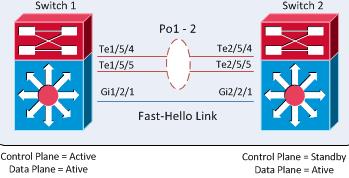

1CISCO-VSS(config)#int gi1/2/1
1CISCO-VSS(config-if)#dual-active fast-hello
1CISCO-VSS(config-if)#no shut
1CISCO-VSS(config-if)#int gi2/2/1
1CISCO-VSS(config-if)#dual-active fast-hello
1CISCO-VSS(config-if)#no shut
1CISCO-VSS(config-if)#
*Sep 15 13:01:20.747: %VSDA-SW2_SPSTBY-5-LINK_UP: Interface Gi2/2/1 is now dual-active detection capable
*Sep 15 13:01:21.759: %VSDA-SW1_SP-5-LINK_UP: Interface Gi1/2/1 is now dual-active detection capable
- Configure the switch priority (optional)
My suggestion is to statically define the switch priority (an higher-priority value assumes the active virtual switch role):
1CISCO-VSS(config)#switch virtual domain 100
1CISCO-VSS(config-vs-domain)#switch 1 priority 110
1CISCO-VSS(config-vs-domain)#switch 2 priority 90
Changing the priority, a log message is generated:
%VSLP-SW1_SP-5-RRP_RT_CFG_CHG: Configured priority value is different from operational value.

Change will take effect after config is saved and switch 1 is reloaded.
%VSLP-SW2_SPSTBY-5-RRP_RT_CFG_CHG: Configured priority value is different from operational value.

Change will take effect after config is saved and switch 1 is reloaded.
Note: the switch priorities affect role determination if both virtual switches are initiated simultaneously . If either switch (regardless of priority) is initiated prior to the subsequent switch, it always assumes the role of the active virtual switch.
After these steps, the VSS configuration is completed!
Multichassis EtherChannel
The multichassis EtherChannel (MEC) is another term to identify an etherchannel that allows a connected node to terminate the EtherChannel across the two physical Cisco Catalyst 6500 Series. In this example the “1CISCO-L2″ switch is connected to the 1CISCO-VSS using a MEC.
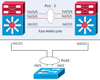

From the point of view of the 1CISCO-L2, the 1CISCO-VSS is a single device (like a stack):
1CISCO-L2#show cdp neighbors
Capability Codes: R - Router, T - Trans Bridge, B - Source Route Bridge
S - Switch, H - Host, I - IGMP, r - Repeater, P - Phone,
D - Remote, C - CVTA, M - Two-port Mac Relay
Device         Local         Capability    Platform      Port ID
1CISCO-     Gig 0/             R S I       WS-C6509-    Gig 1/1/1
1CISCO-     Gig 0/             R S I       WS-C6509-    Gig 2/1/1
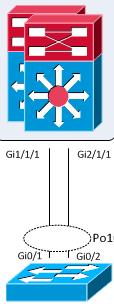

For these reasons, on the 1CISCO-L2 is possible define the port-channel10 with the interfaces Gi0/1 and Gi0/2.
Useful show commands
To show basic VSS informations:
1CISCO-VSS#show switch virtual
Switch mode : Virtual Switch
Virtual switch domain number : 100
Local switch number : 1
Local switch operational role: Virtual Switch Active
Peer switch number : 2
Peer switch operational role : Virtual Switch Standby
To find informations about fast-hello detection:
1CISCO-VSS#show switch virtual dual-active fast-hello
Fast-hello dual-active detection enabled: Yes
Fast-hello dual-active interfaces:
      Local     Peer     Remote State
---------------------------------------------------
Gi1/2/    Link         Gi2/2/      Link up
To identify the role/priority of the two switches:
1CISCO-VSS#show switch virtual role
To find more informations about the VSS status:
1CISCO-VSS#show switch virtual redundancy
My Switch Id = 1
Peer Switch Id = 2
Last switchover reason = none
Configured Redundancy Mode = sso
Operating Redundancy Mode = sso

Switch 1 Slot 5 Processor Information :
-----------------------------------------------
Current Software state = ACTIVE
Uptime in current state = 26 weeks, 4 days, 10 hours, 57 minutes
Image Version = Cisco IOS Software, s72033_rp Software (s72033_rp-ADVENTERPRISEK9-M), Version 15.1(2)SY, RELEASE SOFTWARE (fc4)
Technical Support: http://www.cisco.com/techsupport
Copyright (c) 1986-2013 by Cisco Systems, Inc.
Compiled Wed 04-Sep-13 13:05 by prod_rel_team
BOOT = bootdisk:s72033-adventerprisek9-mz.151-2.SY.bin,12;
Configuration register = 0x2102
Fabric State = ACTIVE
Control Plane State = ACTIVE

Switch 2 Slot 5 Processor Information :
-----------------------------------------------
Current Software state = STANDBY HOT (switchover target)
Uptime in current state = 2 weeks, 3 days, 3 hours, 51 minutes
Image Version = Cisco IOS Software, s72033_rp Software (s72033_rp-ADVENTERPRISEK9-M), Version 15.1(2)SY, RELEASE SOFTWARE (fc4)
Technical Support: http://www.cisco.com/techsupport
Copyright (c) 1986-2013 by Cisco Systems, Inc.
Compiled Wed 04-Sep-13 13:05 by prod_rel_team
BOOT = bootdisk:s72033-adventerprisek9-mz.151-2.SY.bin,12;
Configuration register = 0x2102
Fabric State = ACTIVE
Control Plane State = STANDBY
Note: After the VSS conversation, some “show” commands have the feature to view the output of individual switch! For instance, to see the modules of the second switch use “show module switch 2″.
Reload commands:
To reload a single unit:
# redundancy reload shelf
where either Switch 1 or Switch 2 can be specified.
To force a switchover:
# redundancy force-switchover
References:
- http://www.cisco.com/…/configuration/guide/book/vss.html
- http://www.cisco.com/…/network-modules/white_paper_c11_429338.pdf

