A brief introduction to FabricPath

FabricPath is a technology which combines the benefits of Routing protocols, here will be Intermediate-System-to-Intermediate-System (IS-IS), and Layer 2 Network Ethernet environments.

To list some of FabricPath advantages:

  • MAC Address scalability by Conversational Learning
  • No spanning-tree anymore, hurray! Each switch will have its own view of Layer 2 topology and calculates the L2 topology using SPF calculation.
  • Equal cost multipath forwarding for Unicast Layer 2 traffic!
  • Makes any kind of topology possible!
  • Configuration/Administration is not a hassle anymore
  • Loop prevention/mitigation by having a TTL field in the frames

Switch-ID

We can refer to FabricPath as “Routing MAC Addresses” or “Layer 2 over Layer 3”, but it doesn’t mean that FabricPath ports have an IP Address! In a FabricPath topology, each device is dynamically assigned a “switch-id” via Dynamic Resource Allocation Protocol (DRAP), and L2 forwarding table is populated based on reachability to each switch-id.

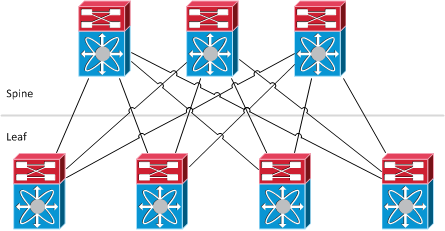
Function types in FabricPath

  • Leaf: This is where Classic Ethernet devices are connected to. It’s the point of “MAC to switch-id” mapping. Traffic is looked up in the L2 forwarding table and then encapsulated into a MAC-in-MAC frame whose destination switch-id is the switch which the destination host is connected to. FabricPath is only supported on Cisco Nexus 5500 with NX-OS 5.1(3)N1(1) and higher as the edge (access) device in FabricPath topology.
  • Spine: Cisco Nexus 7000 is supported as the aggregation device in FabricPath topology with NX-OS 5.1(1) and higher, but only based on F1 line cards. Layer 3 forwarding could be gained by adding M1 series cards.

Continue reading “A brief introduction to FabricPath”

Share this!

Aggregated Ethernet not showing up in JunOS!

In case you have configured an Aggregated-Ethernet (ae) interface on your juniper device, and it doesn’t show up in show interface and show lacp interfaces, then you should take a look at the following:

moghaddas@ex4500> show configuration chassis aggregated-devices ethernet device-count device-count 9;
Share this!

Cisco 6500 VSS Configuration

It’s an old draft from 2010. Recently I was designing a network which VSS was on the topics, so it reminded me of the draft.

The Cisco Catalyst 6500 Series Virtual Switching System (VSS) allows the clustering of two chassis together into a single, logical entity. This technology allows for enhancements in all areas of network design, including high availability, scalability, management, and maintenance.

The Virtual Switching System is created by converting two standalone Catalyst 6500 systems to a Virtual Switching System. The conversion is a one-time process that requires a few simple configuration steps and a system reload. Once the individual chassis reload, they are converted into the Virtual Switching System.

All control plane functions are centrally managed by the active supervisor engine of the active virtual switch chassis, including:

  • Management(Simple Network Management Protocol [SNMP], Telnet, Secure Shell [SSH] Protocol, etc.)
  • Layer 2 Protocols (bridge protocol data units [BPDUs], protocol data units [PDUs], Link Aggregation Control
    Protocol [LACP], etc.)
  • Layer 3Protocols (routing protocols, etc.)
  • Software data path

The requirements to convert the 6500 into a Virtual Switching System are:

  • The VSS requires Supervisor Engine 720 with 10-GigabitEthernet ports. You must use either two VS-S720-10G-3C or two VS-S720-10G-3CXL supervisor engine modules.
  • The VSS requires 67xx seriesswitching modules.
  • The VSLEtherChannel supports only 10-Gigabit Ethernet ports.

Continue reading “Cisco 6500 VSS Configuration”

Share this!

IPX Vol.1 Switching Notes

Downstream switches inherit timers from the root (of each VLAN)

  • BPDUgurad blocks incoming BPDUs.
  • BPDUfilter blocks outgoing BPDUs.
  • bpdufilter default and bpduguard default work in conjunction with portfast default.
  • spanning-tree guard loop  is similar to UDLD, but users STP BPDU keepalive.
show spanning-tree mst [detail]
In MST, load-balancing with cost/port-priority is the same as CST, PVST.
interface f0/0
spanning-tree mst 1 cost 1
spanning-tree mst 2 port-p 0

All switches in the L2 transit path should know about the RSPAN remote-vlan, and the interconnections should be trunk. Remember to remove pruning for RSPAN VLAN from trunks.

IPphone tags voice traffic with CoS 5.

switchport voice vlan dot1p instructs the IP-phone to apply VLAN0 and CoS 5, so both Voice & Data share the same VLAN.

switchport voice vlan  automatically applies portfast.

mls qos trust device ciscoipphone means only trust CoS if received from IP-phone which is detected by CDP.

Fallback Bridging is the concept of bridging non-routed protocols between SVIs or native L3 router interfaces on switches. Similar to CBR and IRB on routers.

bridge 1 protocol vlan-bridge
interface f0/1
 bridge 1
  • PVLAN requires Transparent VTP mode.
  • Whenever a task asks us to optimize a switch for memory or routing, it means “sdm prefer routing“
  • Macros do not accept “interface range”!
  • When filtering traffic using mac-access-list remember to allow Spanning-tree and ARP stuff!

HSRP

  • standby use-bia  : not using the vMAC
  • standby version 2  : Uses 224.0.0.102 for inter-router communications instead of 224.0.0.2
standby 1 ip 150.100.220.1
standby 1 priority  : default is 100
standby 1  : not default
standby 1 track 1 decrement  // same as  standby 1 track Serial0/1/0 20

Remember to add static arp for hosts when filtering ARP in LAB exam. (show arp)

Share this!

Private VLAN

  • Members of an isolated VLAN can only communicate with the promiscuous ports mapped
  • Members of a community VLAN can communicate with members of the same community and the promiscuous ports.

A two-way community acts like a regular community but has the additional aspect of allowing access control lists to check traffic going to and from (two ways) the VLAN and provides enhanced security within a private VLAN.

To configure PVLAN, VTP should be in transparent mode.

  1. Create primary private-vlan
  2. Create isolated/community VLAN
  3. Associating isolated/community VLANs to primary
  4. Configure spanning-tree mode and associating ports to PVLANs
  5. Mapping PVLANs under the primary VLAN interface
  6. To verify: show interface [primary PVLAN] private-vlan mapping

IPExpert, Vol.1, 2.28

You must configure VTP to transparent mode before you can create a private VLAN.
Private VLANs are configured in the context of a single switch and cannot have members on other switches. Private VLANs also carry TLVs that are not known to all types of Cisco switches.

Configuration

SWITCH(config)# vlan primary_number
SWITCH(vlan-config)# private-vlan primary
SWITCH(config)# vlan secondary_number
SWITCH(vlan-config)# private-vlan [isolated | community]
SWITCH(config)# vlan primary_number
SWITCH(vlan-config)# private-vlan association secondary_number_list [add secondary_number_list]
SWITCH(config)# interface type mod/port
SWITCH(config-if)# switchport
SWITCH(config-if)# switchport mode private-vlan host
SWITCH(config-if)# switchport mode private-vlan host-association primary_number secondary_number
SWITCH(config)# interface type mod/port
SWITCH(config-if)# switchport
SWITCH(config-if)# switchport mode private-vlan promiscuous
SWITCH(config-if)# switchport mode private-vlan mapping primary_number secondary_number
SWITCH(config)# interface primary_number
SWITCH(config-if)# ip address address mask
SWITCH(config-if)# private-vlan mapping primary_number secondary_number
show vlan private-vlan type
show interface private-vlan mapping
show interface type mod/port switchport
Share this!