Cisco ACI – 2 – Provisioning a fabric

As mentioned in the last post, let’s make the first step happen: Making an online fabric!

Turn on the UCS server which you have chosen for the APIC role!
It’s presumed that we start with CIMC utility to setup the APIC. As it is with all other Cisco CLIed products, we get a simple wizardish script as below:

I’m sure you have the Cisco ACI Fundamentals open, but let me take a look into some of the parameters which was asked:

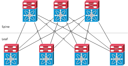
  • TEP Address pool: Every leaf and spine node in the fabric, will be automatically assigned at least one Tunnel End Point address.
  • Multicast Address pool: will be used for multicast traffic through the network
  • VLAN ID: is used for communication inside the fabric infrastructure network

After a while, the APIC would be up and accessible via the web management interface using the OOB IP address. Now, we have to discover the physical switching nodes.

I never like to go through GUI, so I just name the steps and mention the more important parts.

  1. From the GUI go to: Fabric tab >> Inventory sub-menu
  2. Click on Fabric Membership (left)
  3. Hence your APIC is at least connected to one Nexus switch, you should see a single leaf node. LLDP is the magic which makes this happen. But we have not yet registered the switch, so there is no ID, name and IP listed.
  4. Double click on each field and simply assign a node ID. After a short break, you will see an IP address for the node. Notice that the IP is assigned from the range we specified for TEP pool during the wizard.
  5. The switch is registered!

Now, we have officially a leaf node, the rest of network will be discovered and you can see the spine nodes appearing on the Fabric Membership page. As you guess, we have to register these nodes the same as the leaf switch. As the result, the remaining switches will pop up and available for membership.

Once all the switching topology –including other leaf nodes– is discovered, we can initialise the same setup procedure for other APICs and form an APIC Cluster. Keep in mind that we have to use different controller ID, management IP, etc.

By the time all APICs are running, the fabric is almost ready and we can see a graphical topology via Fabric | Inventory section in the APIC GUI.

One more thing to do would be to configure the switching nodes with management IP so they can be managed directly. This is done inside Tenants tab and then the Mgmt tenant, where on the left there is Node Management Addresses which let us to configure management IPs for every single fabric node. The next step is to configure at least an Out-of-Band Contract under Security Policies menu, in order to permit traffic into OOB management interfaces. Finally, under Node Management EPGs, we should assign the OOB contract to our OOB EPG.

Share this!

A brief introduction to FabricPath

FabricPath is a technology which combines the benefits of Routing protocols, here will be Intermediate-System-to-Intermediate-System (IS-IS), and Layer 2 Network Ethernet environments.

To list some of FabricPath advantages:

  • MAC Address scalability by Conversational Learning
  • No spanning-tree anymore, hurray! Each switch will have its own view of Layer 2 topology and calculates the L2 topology using SPF calculation.
  • Equal cost multipath forwarding for Unicast Layer 2 traffic!
  • Makes any kind of topology possible!
  • Configuration/Administration is not a hassle anymore
  • Loop prevention/mitigation by having a TTL field in the frames

Switch-ID

We can refer to FabricPath as “Routing MAC Addresses” or “Layer 2 over Layer 3”, but it doesn’t mean that FabricPath ports have an IP Address! In a FabricPath topology, each device is dynamically assigned a “switch-id” via Dynamic Resource Allocation Protocol (DRAP), and L2 forwarding table is populated based on reachability to each switch-id.

Function types in FabricPath

  • Leaf: This is where Classic Ethernet devices are connected to. It’s the point of “MAC to switch-id” mapping. Traffic is looked up in the L2 forwarding table and then encapsulated into a MAC-in-MAC frame whose destination switch-id is the switch which the destination host is connected to. FabricPath is only supported on Cisco Nexus 5500 with NX-OS 5.1(3)N1(1) and higher as the edge (access) device in FabricPath topology.
  • Spine: Cisco Nexus 7000 is supported as the aggregation device in FabricPath topology with NX-OS 5.1(1) and higher, but only based on F1 line cards. Layer 3 forwarding could be gained by adding M1 series cards.

Continue reading “A brief introduction to FabricPath”

Share this!

Cisco ACI – 1 – High level architecture overview

What is Application Centric Infrastructure (ACI)?
Simplest definition: A data center architecture which abstracts network building blocks (VLAN, VRF, Subnets, etc.) using policies!

In ACI architecture, from the HLD point of view, Nexus 9000 will act as the physical switching fabric, and Application Policy Infrastructure Controller (APIC), in the form of a clustered policy management system, will take care of policies.

As I called the word “fabric”, you can imagine a fabricpath-like topology, but:

  • spines are not connected to each other
  • leaves are not connected to each other
  • leaves are connected to all spines
  • all other connectivities are via the leaf nodes (no thing will be directly attached to spines!)

So, tell me where an APIC should be connected?
Obviously, to a leaf!

It’s all about policies! Policies define all the system configuration/administration. Also, a policy model define how applications and attached systems communicate.

ACI defines some new concepts, such as Service Graphs, Contracts, Filters, Application Profiles, Endpoint groups, etc. Hopefully, I’ll cover them in future posts.

By the concept of Service Graph, ACI is able to be highly integrated with Layer 4 to Layer 7 services devices. A Service Graph could be translated as a description of “where a service, such as a firewall, should be placed in the traffic flow”.

Ok, before diving into anything else, the first step would be provisioning a fabric and let it on. Interested? It will be more interesting in the next post!

By the way, I forgot to mention that, it would be nice to have Cisco ACI Fundamentals open while reading this.

Share this!

ToR & EoR Data Center Designs

This post is my snippet of Brad Hedlund article about ToR and EoR design which is accessible via the following link:
http://bradhedlund.com/2009/04/05/top-of-rack-vs-end-of-row-data-center-designs/

Top of Rack Design

ToR is sometimes called In-Rack design.

Benefits:
  • All copper cabling for servers stays within the rack as relatively
  • there is no need to for a large copper cabling infrastructure
  • Any network upgrades or issues with the rack switches will generally only affect the servers within that rack
  • any future support of 40 or 100 Gigabit on twisted pair will likely have very short distance limitations (in-rack distances). This too is another key factor why Top of Rack would be selected over End of Row.

Continue reading “ToR & EoR Data Center Designs”

Share this!