MPLS Fundamentals: 6 – MPLS TE

The role of TE is to get the traffic from edge to edge in the network in the most optimal way.

  • MPLS TE takes into account the configured (static) bandwidth of links.
  • MPLS TE takes link attributes into account (for instance, delay, jitter).
  • MPLS TE adapts automatically to changing bandwidth and link attributes.

MPLS TE allows for a TE scheme where the head end router of a label switched path (LSP) can calculate the most efficient route  through the network toward the tail end router of the LSP. The head end router can do that if it has the topology of the network.  Furthermore, the head end router needs to know the remaining bandwidth on all the links of the network. Finally, you need to  enable MPLS on the routers so that you can establish LSPs end to end. The fact that label switching is used and not IP forwarding  allows for source-based routing instead of IP destination-based routing. That is because MPLS does forwarding in the data plane by  matching an incoming label in the label forwarding information base (LFIB) and swapping it with an outgoing label.

Therefore, it is the head end label switching router (LSR) of the LSP that can determine the routing of the labeled packet, after all  LSRs agree which labels to use for which LSP.

Share this!

MPLS Fundamentals: 4 – CEF

Process Switching

Process switching is the slowest of all switching methods. When switching a packet through the router, a Cisco IOS process copies  the packet to the CPU memory and looks up the destination IP address in the IP routing table. Based on the outcome of this lookup,  the process switches out the packet on a particular interface after it does some housekeeping on the IP header.

Fast Switching

The first packet for a destination that arrives is process switched. The switching of the first packet by the central CPU gives the CPU  the opportunity to build a cache. This cache is called the IP fast switching route cache and is used by the interrupt code to switch  subsequent packets for the same destination.

If a prefix changes in the routing table, the entry in the fast switching cache is invalidated, and the first packet for a destination has  to be process-switched again to build the new entry in the route cache.

Each IP prefix entry in the route cache has an outgoing interface, next hop, and Layer 2 rewrite field. This Layer 2 rewrite (or MAC  rewrite) is the information that the router needs to change in the Layer 2 frame header when the frame is rebuilt so that it can be  sent on the outgoing interface. Continue reading “MPLS Fundamentals: 4 – CEF”

Share this!

MPLS Fundamentals: 2 – Forwarding Labeled Packets

CEF switching is the only IP switching mode that you can use to label packets. Other IP switching modes, such as fast switching, cannot be used, because the fast switching cache does not hold information on labels. Because CEF switching is the only IP switching mode that is supported in conjunction with MPLS, you must turn on CEF when you enable MPLS on the router.

show mpls forwarding-table

The local label (or tag) is the label that this LSR assigns and distributes to the other LSRs.
If this LSR receives a packet with top label 16, it removes all labels and forwards the packet as an IP packet, because the outgoing label (tag) is Untagged.

show mpls forwarding-table

The incoming label 23 is swapped with label 20, and label 16 is pushed onto label 20.

Continue reading “MPLS Fundamentals: 2 – Forwarding Labeled Packets”

Share this!

MPLS Fundamentals: 1 – Architecture

  • Ingress LSRs —Ingress LSRs receive a packet that is not labeled yet, insert a label (stack) in front of the packet, and send it on a data link. One that is doing imposition is an ingress LSR
  • Egress LSRs—Egress LSRs receive labeled packets, remove the label(s), and send them on a data link. Ingress and egress LSRs are edge LSRs. One that does disposition is an egress LSR.

A Forwarding Equivalence Class (FEC) is a group or flow of packets that are forwarded along the same path and are treated the same with regard to the forwarding treatment.

The same FEC have the same label. However, not all packets that have the same label belong to the same FEC, because their EXP values might differ; the forwarding treatment could be different, and they could belong to a different FEC. The router that decides which packets belong to which FEC is the ingress LSR. This is logical because the ingress LSR classifies and labels the packets.

All packets with a destination IP address for which the IP lookup in the routing table recourses to the same BGP next-hop address will be mapped to the same FEC.

Labels are local to each pair of adjacent routers.

The implementation for distance vector routing protocols (such as EIGRP) is straightforward, because each router originates a prefix from its routing table. The router then just binds a label to that prefix.

For link state routing protocols, a separate protocol is preferred to distribute the labels.

BGP is a routing protocol that can carry prefixes and distribute labels at the same time.

These received bindings become remote bindings. The neighbors then store these remote and local bindings in a special table, the label information base (LIB).

You can have one label per prefix or one label per prefix per interface, but the LSR gets more than one remote binding because it usually has more than one adjacent LSR.

The routing table (sometimes called the routing instance base, or RIB) determines what the next hop of the IPv4 prefix is. The LSR chooses the remote binding received from the downstream LSR, which is the next hop in the routing table for that prefix. It uses this information to set up its label forwarding information base (LFIB) where the label from the local binding serves as the incoming label and the label from the one remote binding chosen via the routing table serves as the outgoing label.

LDP does not bind labels to BGP IPv4 prefixes.

All these remote bindings are found in the LIB. The LFIB chooses only one of the possible outgoing labels from all the possible remote bindings in the LIB and installs it in the LFIB. The remote label chosen depends on which path is the best path found in the routing table.

It is the egress LSR that created the label binding for that FEC, and it knows what that FEC is.

  • Independent LSP Control mode: In this control mode, each LSR creates a local binding for a particular FEC as soon as it recognizes the FEC. Usually, this means that the prefix for the FEC is in its routing table.
  • Ordered LSP Control mode: an LSR only creates a local binding for a FEC if it recognizes that it is the egress LSR for the FEC or if the LSR has received a label binding from the next hop for this FEC.

If the LSR were running in Independent LSP Control mode, it would assign a local binding for each IGP prefix in the routing table. If the LSR were running in Ordered LSP Control mode, this LSR would only assign a local label binding for the IGP prefixes that are marked as connected in its routing table and also for the IGP prefixes for which it has already received a label binding from the next-hop router (as noted in the routing table). Cisco IOS uses Independent LSP Control mode. ATM switches that are running Cisco IOS use Ordered LSP Control mode by default.

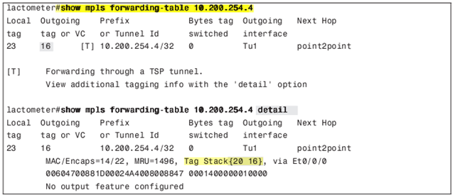
The label stack sits in front of the transported packet. If the transported packet is an IP packet, the label stack is behind the Layer 2 header but before the IP header.

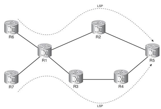
An ordered sequence of LSRs is a label switched path (LSP). A Forwarding Equivalence Class (FEC) is a group or flow of packets that receive the same forwarding treatment throughout the MPLS network. The FEC is thus determined by the label stack and the EXP bits in the label.

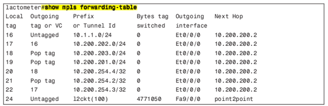
The LIB is the table that stores the label bindings, whereas the LFIB is the lookup table that forwards labeled packets.

Share this!

MPLS Fundamentals: 3 – LDP

Basic MPLS LDP Configuration

224.0.0.2 group IP multicast address. The UDP port used for LDP is 646.

LDP Discovery

show mpls ldp discovery detail
show mpls interfaces

LDP discovery timers manipulation

mpls ldp discovery {hello {holdtime | interval } seconds

The default value for holdtime is 15 seconds for link Hello messages, and the default value for interval is 5 seconds.
If the two LDP peers have different LDP Hold times configured, the smaller of the two values is used as the Hold time for that LDP discovery source.

Cisco IOS might overwrite the configured LDP Hello interval. It will choose a smaller LDP Hello interval than configured so that it can send at least three LDP Hellos before the Hold time expires. (At least nine Hellos are sent in the case of a targeted LDP session)

Continue reading “MPLS Fundamentals: 3 – LDP”

Share this!