MPLS Fundamentals: 3 – LDP

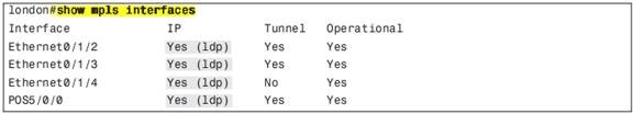
Basic MPLS LDP Configuration

224.0.0.2 group IP multicast address. The UDP port used for LDP is 646.
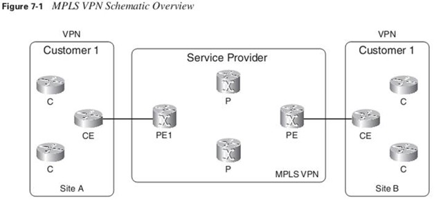
LDP Discovery

show mpls ldp discovery detail
show mpls interfaces

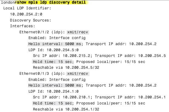
LDP discovery timers manipulation

mpls ldp discovery {hello {holdtime | interval } seconds

The default value for holdtime is 15 seconds for link Hello messages, and the default value for interval is 5 seconds.
If the two LDP peers have different LDP Hold times configured, the smaller of the two values is used as the Hold time for that LDP discovery source.

Cisco IOS might overwrite the configured LDP Hello interval. It will choose a smaller LDP Hello interval than configured so that it can send at least three LDP Hellos before the Hold time expires. (At least nine Hellos are sent in the case of a targeted LDP session)

Continue reading “MPLS Fundamentals: 3 – LDP”

Share this!

RT & RD difference

  • It’s given that customers of a Service Provider will have overlapping IP addressing in their VPNs, e.g. you will have more than two customers who use the 10.0.0.0/8 network.  The RD is how you tell them apart.  If you have customer “A” with RD “A” and customer “B” with RD “B” the routes “A:10.0.0.0/8” and “B:10.0.0.0/8” become unique.  This is all the RD does.

What is an RD? An RD is a 64 bit value that is attached to the customer’s IPv4 address, to make it a Unique 96 bit address called VPNv4. These addresses are ONLY exchanged between the PE routers.

Once the PE router attaches the RD to the CE routes, it then sends the VPNv4 address/es to the other PE router/s. The receiving PE router strips the RD from the VPNv4 prefix, and it s left with an IPv4 address.

  • The Route Target tells you which VRF table the route belongs to.  You have to separate the two attributes because sometimes you want the same route to belong to multiple VRF tables.   This is common in what’s known as “Central Services VPNs”. For example if the Service Provider hosts email for customers, that route to the mail server would have to be in the routing table of multiple customers.  This doesn’t break the rule of the route having to be unique though, which is what the RD does.

NOW  How does the receiving PE know which VRF does the IP address belong to? The answer is  Route-Target .

The  Route-target  is a BGP extended community that indicates which routes should be exported from a given VRF or imported into a given VRF.

Share this!

IPExpert CoD: MPLS-VPN

This post contains my notes from an old version of IPX Class on Demand by Joe Astorino.

RD has no special meaning—it is only used to make potentially overlapping IPv4 addresses globally unique

Route Targets are additional attributes attached to VPNv4 BGP routes to indicate VPN membership

Export Route Targets identifying VPN membership are appended to customer route when it is converted into VPNv4 route

RD & RT are extended BGP communities; neighbor send-community extended is required!

RR for VPNv4 does not need to be the same as RR of IPv4.

PE imposes 2 labels, the one if from LDP, and the bottom one is from VPNv4 address-family.

Each bgp address-family is a different RIB.

  • Import policy means that routes will come from the VPN extended community
  • Export policy means that routes will go to the VPN extended community

ARF –Automatic Route Filtering:  Only VPN information matching a locally configured RT will be imported
Could be disabled: no default bgproute-target filter

By default, when running OSPF over Frame-Relay and network type is anything except point-to-multipoint, on a spoke, the nexthop for a route originated  from another spoke will be that spoke.
But when the network type is point-to-multipoint, the nexthop will be the hub, and a host route for each spoke will exist.
So make sure to use point-to-multipoint when using MPLS.

RIP/EIGRP address-family version and summarization is different form the RIP/EIGRP’s itself.

When the customer needs the same AS on multiple sites, the AS Override feature should be triggered. So the PE will override its (prepend). Another way to handle this requirement is using allowas-in. Continue reading “IPExpert CoD: MPLS-VPN”

Share this!

MPLS Fundamentals: 5 – MPLS-VPN

Most popular were Frame Relay or ATM technologies, providing VPN service at Layer 2. The provider had a Frame Relay or ATM backbone and supplied Layer 2 connectivity to the customer routers. This was commonly referred to as the  overlay model.

The service provider might have actually owned or managed the edge routers that were connected to the customer network. The point is that the routers were physically at the customer premises.

Peer-to-peer VPN networks existed, but they were not popular. The main reason is that they were not easy to deploy and maintain because they needed distribute lists, IP packet filters, or GRE tunnels. As explained in Chapter 1, MPLS VPN is an example of a highly scalable peer-to-peer VPN model.

The CE router does not peer with any of the CE routers from the other sites across the service provider network, as with the overlay model. The name  peer-to-peer model  is derived from the fact that the CE and PE form a peer at Layer 3.

Virtual routing/forwarding (VRF): is a VPN routing and forwarding instance. It is the name for the combination of the VPN routing table, the VRF Cisco Express Forwarding (CEF) table, and the associated IP routing protocols on the PE router.

A PE router holds the global IP routing table, but also a VRF routing table per VPN connected to the PE. Continue reading “MPLS Fundamentals: 5 – MPLS-VPN”

Share this!