Most popular were Frame Relay or ATM technologies, providing VPN service at Layer 2. The provider had a Frame Relay or ATM backbone and supplied Layer 2 connectivity to the customer routers. This was commonly referred to as the overlay model.
The service provider might have actually owned or managed the edge routers that were connected to the customer network. The point is that the routers were physically at the customer premises.
Peer-to-peer VPN networks existed, but they were not popular. The main reason is that they were not easy to deploy and maintain because they needed distribute lists, IP packet filters, or GRE tunnels. As explained in Chapter 1, MPLS VPN is an example of a highly scalable peer-to-peer VPN model.
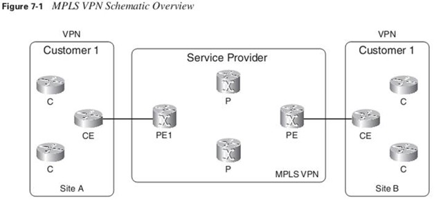

The CE router does not peer with any of the CE routers from the other sites across the service provider network, as with the overlay model. The name peer-to-peer model is derived from the fact that the CE and PE form a peer at Layer 3.
Virtual routing/forwarding (VRF): is a VPN routing and forwarding instance. It is the name for the combination of the VPN routing table, the VRF Cisco Express Forwarding (CEF) table, and the associated IP routing protocols on the PE router.
A PE router holds the global IP routing table, but also a VRF routing table per VPN connected to the PE.
The interface on the PE router toward the CE router can belong to only one VRF. As such, all IP packets received on the VRF interface are unambiguously identified as belonging to that VRF. Because there is a separate routing table per VPN, there is a separate CEF table per VPN to forward these packets on the PE router. This is the VRF CEF table. As with the global routing table and the global CEF table, the VRF CEF table is derived from the VRF routing table.
You create the VRF on the PE router with the ip vrf command. You use the ip vrf forwarding command to assign PE-CE interfaces on the PE router to a VRF. You can assign an interface to only one VRF, but you can assign several interfaces to the same VRF. The PE router then automatically creates a VRF routing table and CEF table.
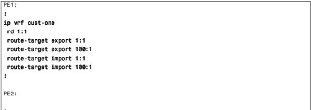
Configuring a VRF
ip vrf cust-one
 rd 1:1
 route-target export 1:1
 route-target import 1:1
!
interface Serial5/1
 ip vrf forwarding cust-one
 ip address 10.10.4.1 255.255.255.0
!
sydney#show ip route vrf cust-one
sydney#show ip cef vrf cust-one
Because the VRF instance is associated with interfaces, only IP packets that are entering the PE router via those VRF interfaces are forwarded according to that VRF CEF table.
In Cisco IOS, CEF is the only switching method supported for forwarding IP packets from the VRF interface. As such, CEF must be enabled globally on all PE routers and all VRF interfaces.
If the customers had overlapping IP addressing, the routing would be wrong. To solve this problem, the concept of RDs was conceived to make IPv4 prefixes unique. The basic idea is that each prefix from each customer receives a unique identifier (the RD) to distinguish the same prefix from different customers. A prefix derived from the combination of the IPv4 prefix and the RD is called a vpnv4 prefix. MP-BGP needs to carry these vpnv4 prefixes between the PE routers.
Each VRF instance on the PE router must have one RD assigned to it. This 64-bit value can have two formats: ASN:nn or IP-address:nn , where nn represents a number.
The RD does not impose semantics; it is just used to uniquely identify the VPN routes. This is needed because the IPv4 routes from one customer might be overlapping with the IPv4 routes from another. The combination of the RD with the IPv4 prefix provides a vpnv4 prefix, of which the address is 96 bits long. The mask is 32 bits long.
If you take an IPv4 prefix 10.1.1.0/24 and an RD 1:1, the vpnv4 prefix becomes 1:1:10.1.1.0/24.
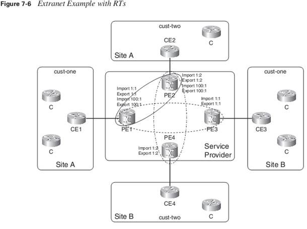
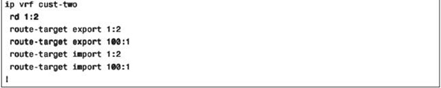
If RDs were just used to indicate the VPN, communication between sites of different VPNs would be problematic. A site of Company A would not be able to talk to a site of Company B because the RDs would not match. The concept of having sites of Company A being able to talk to sites of Company B is called extranet VPN.
Exporting an RT means that the exported vpnv4 route receives an additional BGP extended community—this is the RT—as configured under ip vrf on the PE router, when the route is redistributed from the VRF routing table into MP-BGP. Importing an RT means that the received vpnv4 route from MP-BGP is checked for a matching extended community—this is the route target—with the ones in the configuration. If the result is a match, the prefix is put into the VRF routing table as an IPv4 route. If a match does not occur, the prefix is rejected.
The command to configure RTs for a VRF is:
route-target {import | export | both } route-target-ext-community
The keyword both indicates both import and export.
When configuring a VRF with several sites that belong to one VPN, without having to communicate to sites belonging to another VPN, you just need to configure one RT to be imported and exported on all the PE routers with a site belonging to that VRF. This is the simple case of an intranet.
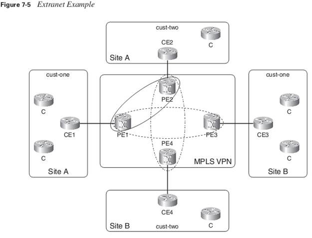
When you have sites belonging to one VPN that need to be able to communicate with sites from another VPN (the extranet case), pay attention to the way to configure the RTs correctly. Figure 7-5 shows an extranet example.
Extranet Configuration


How does the egress PE router know which VRF the packet belongs to?
This information is not in the IP header, and it cannot be derived from the IGP label, because this is used solely to forward the packet through the service provider network. The solution is to add another label in the MPLS label stack. This label indicates which VRF the packet belongs to. Therefore, all customer packets are forwarded with two labels: the IGP label as the top label and the VPN label as the bottom label. The VPN label must be put on by the ingress PE router to indicate to the egress PE router which VRF the packet belongs to.
How does the egress PE router signal to the ingress PE router which label to use for a VRF prefix? Because MP-BGP is already used to advertise the vpnv4 prefix, it also signals the VPN label (also referred to as the BGP label) that is associated with the vpnv4 prefix.
A VPN label usually indicates the next hop that the packet should be forwarded onto on the egress PE router. Therefore, most of the time, its purpose is to indicate the correct CE router as the next hop of the packet.
P routers use the IGP label to forward the packet to the correct egress PE router. The egress PE router uses the VPN label to forward the IP packet to the correct CE router.
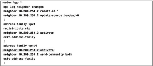
You use the address family vpnv4 under the router bgp process to configure the vpnv4 BGP sessions and parameters, which the PE routers need.
You use the address family ipv4 vrf vrf-name under the router bgp process on the PE routers to configure the BGP sessions and parameters toward the CE routers, across the VRF interfaces.
show ip bgp vpnv4 {all | rd route-distinguisher | vrf vrf-name } [ rib-failure ] [ ip-prefix/length [longer-prefixes ] [ output-modifiers ]] [ network-address [ mask] [ l o n g e r – p r e f i x e s][l a b e l s]
However, if you use the command with the vrf keyword on a route reflector (RR), it might not show you routes. The RR might not have VRFs configured, because it is probably just used to reflect the vpnv4 routes. In that case, you should use the command with the rd keyword to look at specific vpnv4 routes
A BGP speaker only assigns a label to a prefix for which it is the next hop. This is an important rule to remember when looking at the behavior of a BGP RR for vpnv4 routes.
First, you need to define the BGP neighbor in the global part of the BGP configuration. Then you need to enable the BGP neighbor in the address family vpnv4 by specifying the activate keyword.
Only BGP extended communities are sent by default to the vpnv4 neighbor. If you want to use standard communities, too, please specify send-community both for the BGP neighbor.

For the prefixes with 0.0.0.0 as the next hop in Example 7-15, no outgoing label has been received. This is because the prefixes are learned from VRF interfaces and packets should be forwarded unlabeled toward the CE router.

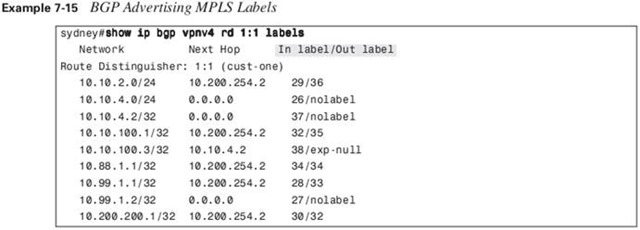
Each vpnv4 prefix is assigned a unique MPLS label in Cisco IOS. This is the default Cisco IOS behavior.
RRs peer with the BGP speakers in a cluster, but the BGP speakers in the cluster do not need to peer with each other any more if they peer with the RRs. The RRs just forward or reflect all the BGP routes they receive. If you want to use RRs with MPLS VPN, the RRs should reflect vpnv4 prefixes, which carry labels. RRs only change the label if they become the next hop for the routes, which they usually do not. RRs that do become the next hop for the iBGP route are in the forwarding path. This means that they have to forward the traffic for those routes.
RRs should not forward traffic, but just reflect BGP routes
RRs differ in another way from the other BGP speakers (the PE routers) in the MPLS VPN network. They do not reject vnpv4 routes when the RT is not configured for acceptance on the RRs. A PE router that receives a vpnv4 route for which any of the RTs is not imported into a VRF rejects the route.
It is a good idea to have at least two RRs for a subset of the vpnv4 prefixes for redundancy reasons.
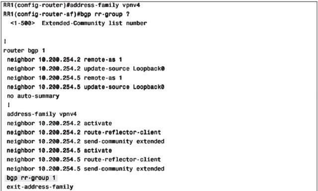
You can subdivide the vpnv4 routes into groups and allow several RRs or several groups of RRs to carry one of those subsets of routes.
bgp rr-group {extcom-list-number} under the address family vpnv4
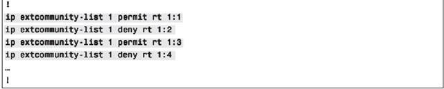
You must specify an extended community list for the RR group. This extended community list specifies the RTs that you want this RR to permit or deny.
Example of RR groups


BGP Multipath is a BGP feature whereby the selection process still selects one BGP path as the best but allows multiple BGP paths to be installed in the routing table.
BGP Multipath Commands
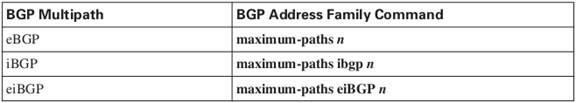

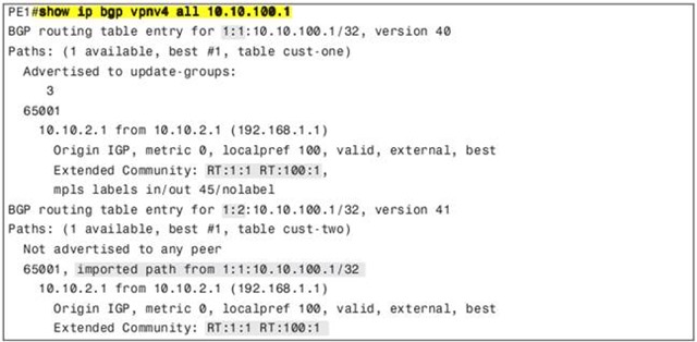
The import keyword indicates how many routes can be imported from one VRF into another.
The RDs of the vpnv4 routes that are received on PE3 and the configured RD of VRF cust-two differ, though, so the import keyword for iBGP Multipath is needed here.


When an IP packet enters the ingress PE router from the CE, the ingress PE router looks up the destination IP address in the VRF cust-one CEF table. The ingress PE router finds the correct VRF by looking at which interface the packet entered the PE router, and with which VRF table this interface is associated. The specific entry in the VRF CEF table usually indicates that two labels need to be added.
When the ingress and egress PE routers are directly connected, the packets will have only one label—the VPN label. This is true because of penultimate hop popping (PHP).
First, the ingress PE router pushes VPN label 30—as advertised by BGP for the vpnv4 route. This becomes the bottom label. Then, the ingress PE router pushes the IGP label as the top label. This label is the label that is associated with the /32 IGP route for the BGP next-hop IP address.
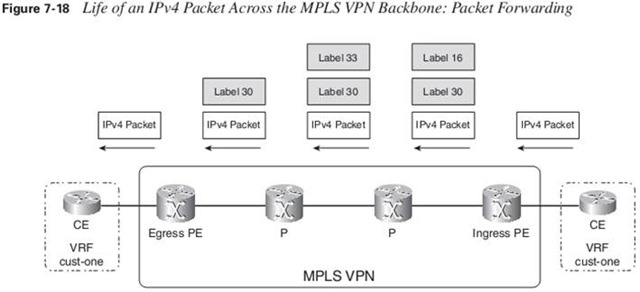
The egress PE router does not have to perform an IP lookup of the destination IP address in the IP header if the outgoing label is No Label. The correct next-hop information is found by looking up the VPN label in the LFIB. Only when the outgoing label is Aggregate does the egress PE router have to perform an IP lookup in the VRF CEF table after the label lookup in the LFIB.
Strictly speaking, the connected routes are not a routing protocol. However, to ensure connectivity, it is best practice to redistribute the connected routes on the PE router into BGP. That way, when the user launches a ping from a CE router to the remote CE router, the return packet is routed back. By default, if the user sends a ping and does not specify the source IP address, it takes as the source IP address of the outgoing interface.
RIPv2:
- Including a subnet mask with the prefixes
- Using the multicast address 224.0.0.9 instead of the broadcast address 255.255.255.255
- Including a next-hop address
- Including a route tag
- Use authentication (optional)
In Cisco IOS, RIPv2 is supported as a PE-CE routing protocol, but RIP version 1 is not.
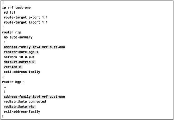
Make sure the default-metric command is configured for RIP. Otherwise, no routes are distributed from BGP to RIP.
RIPv2 VRF configuration

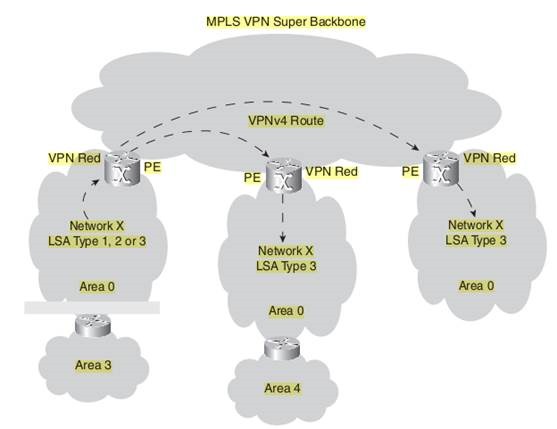
To propagate the customer routes from PE to PE, OSPF is redistributed into iBGP and vice versa on the PE routers. The down side of this is that all OSPF routes become external routes on the remote PE when the routes are redistributed back into OSPF. The result of this would be that all OSPF routes that transverse the MPLS VPN backbone would be less preferable than the routes that did not transverse the backbone but were sent via an intersite link (backdoor link) from one OSPF site to another.
To prevent all redistributed routes from becoming OSPF external prefixes, internal OSPF routes are advertised as summary routes (link-state advertisement [LSA] type 3)—which are interarea routes—on the PE when they are redistributed from BGP back to OSPF.

The normal OSPF route preference dictates that intra-area routes are more preferred than interarea OSPF routes. Because all internal OSPF routes become interarea routes at the remote sites, intra-area routes might still cause a problem becoming interarea routes when a backdoor link exists between sites. The intra-area routes remain intra-area routes across the backdoor link but become interarea routes across the MPLS VPN backbone. Therefore, the intra-area routes that are advertised across the backdoor link are always preferred. To avoid this, you must configure a special link, called a sham link, between the PE routers.
Make sure you have the subnets keyword on the redistribute bgp command under the router ospf process. Otherwise, only classful routes are redistributed. When you are redistributing OSPF into BGP, make sure to configure the appropriate match parameters on the redistribute command so that you can redistribute the proper OSPF type of routes.
Basic OSPF VRF Configuration
ip vrf cust-one
 rd 1:1
 route-target export 1:1
 route-target import 1:1
!
interface Loopback1
 ip vrf forwarding cust-one
 ip address 10.99.1.1 255.255.255.255
!
router ospf 42 vrf cust-one
 router-id 10.99.1.1
 log-adjacency-changes
 redistribute bgp 1 metric 10 subnets
 network 10.10.2.0 0.0.0.255 area 0
!
router bgp 1
 bgp log-neighbor-changes
 neighbor 10.200.254.5 remote-as 1
 neighbor 10.200.254.5 update-source Loopback0
 !
 address-family vpnv4
 neighbor 10.200.254.5 activate
 neighbor 10.200.254.5 send-community extended
 exit-address-family
 !
 address-family ipv4 vrf cust-one
 redistribute connected
 redistribute ospf 42 vrf cust-one metric 10 match internal external 1 external 2
 exit-address-family
london#show ip ospf 42
 Routing Process “ospf 42” with ID 10.99.1.1
   Domain ID type 0x0005, value 0.0.0.42
 Supports only single TOS(TOS0) routes
 Supports opaque LSA
 Supports Link-local Signaling (LLS)
 Supports area transit capability
 Connected to MPLS VPN Superbackbone, VRF cust-one
 It is an area border and autonomous system boundary router
 Redistributing External Routes from,
    bgp 1 with metric mapped to 10, includes subnets in redistribution
…
 Number of areas in this router is 1. 1 normal 0 stub 0 nssa
 Number of areas transit capable is 0
 External flood list length 0
    Area BACKBONE(0)
        Number of interfaces in this area is 2
        Area has no authentication
        SPF algorithm last executed 00:04:35.120 ago
        SPF algorithm executed 25 times
        Area ranges are
        Number of LSA 17. Checksum Sum 0x0E27D6
        Number of opaque link LSA 0. Checksum Sum 0x000000
        Number of DCbitless LSA 0
        Number of indication LSA 0
        Number of DoNotAge LSA 13
        Flood list length 0
When you redistribute both internal and external OSPF routes from OSPF into MP-BGP on the PE router, the PE router uses the OSPF metric to set the BGP MED. The MED is often referred to as the external metric of a BGP route.
If the route type is 1, 2, or 3 (corresponding to LSA types 1, 2, or 3), the remote PE router advertises an interarea summary route (LSA type 3) into the OSPF area.
If the domain ID (by default set equal to the OSPF router process ID) of the route received by a PE router does not match the OSPF process ID of the particular VRF, the route is advertised as an OSPF external route (LSA type 5) type 2 to provide support for networks that are redistributing IP routes between different OSPF processes. If the domain ID does match the OSPF process ID, the route is advertised as an internal route.
You can change the domain ID on the PE router with the command domain-id ospf domain ID.
Normally, a split backbone area requires a virtual link to interconnect the parts. This is not needed for MPLS VPN, though, because iBGP carries the OSPF routes, OSPF routes are re-created on the PE routers, and the MPLS VPN backbone has no flooding. Refer to the next section for one exception; flooding does occur across the MPLS VPN backbone when a sham link is used.
If, however, a site has more than one area, the PE routers must be in area 0 because they are ABRs. If they are not, a virtual link between the PE router and the nearest ABR in the customer site must bring area 0 up to the PE router.
Sham Link
If two sites belong to the same area and are interconnected with a backdoor link, they appear as one area to OSPF. Through the backdoor link, all LSAs are flooded unaltered from one site to the other. This means that intra-area routes stay intra-area routes. The intra-area routes (type 1 and 2 LSAs) are flooded across the backdoor link. They are transformed into interarea routes across the MPLS VPN backbone. That means that the preferred path between the two sites is always the backdoor link because OSPF always prefers the intra-area routes over the interarea routes. This reduces the MPLS VPN service to a mere backup solution in case the backdoor link goes down. The concept of sham link was invented to solve this problem. The sham link is not a real link but a fake one between two PE routers. It is an OSPF intra-area link created between the two PE routers so that they can flood this link in the area connected to both the PE routers. The sham link has two endpoints. The sham link endpoint on each PE router is a /32 IPv4 address from the specific VRF. iBGP must advertise this /32 IPv4 address from one PE to the other as a vpnv4 prefix. The sham link is an unnumbered point-to-point intra-area link that is treated as a demand-circuit link. This means that LSAs are flooded across the sham link, but no periodic refresh flooding occurs across the sham link.
The sham link is included in the shortest path first (SPF) computation, just as any link in OSPF. As LSAs are flooded across the sham link, all OSPF route types can be preserved and do not have to be converted into type 3 or 5 LSAs. If the sham link fails, the default mechanism of sending only type 3 and type 5 LSAs into the site occurs. Routing across the MPLS VPN backbone is still possible if the sham link fails, but the backdoor link is the preferred path for intra-area routes because intra-area routes are still learned that way. You configure the sham link by specifying a source IP address in the VRF on the local PE and a destination IP address in the VRF on the remote PE. In addition, you can specify a cost for the sham link to make it more or less preferred than the backdoor link. The syntax of the sham link command is area area-id sham-link source-address destination-address cost number.
router ospf 42 vrf cust-one
 router-id 10.99.1.1
 log-adjacency-changes
 area 0 sham-link 10.99.1.1 10.99.1.2 cost 10
 redistribute bgp 1 metric 10 subnets
 network 10.10.2.0 0.0.0.255 area 0
london#show ip ospf 42 neighbor
Neighbor ID     Pri   State           Dead Time   Address         Interface
10.200.200.1     1   FULL/DR         00:00:35    10.10.2.1       Ethernet0/1/2
10.99.1.2            0   FULL/  –                 –            10.99.1.2        OSPF_SL2

london#show ip ospf 42 sham-links
Sham Link OSPF_SL2 to address 10.99.1.2 is up
Area 0 source address 10.99.1.1
  Run as demand circuit
  DoNotAge LSA allowed. Cost of using 10 State POINT_TO_POINT,
  Timer intervals configured, Hello 10, Dead 40, Wait 40,
    Hello due in 00:00:03
    Adjacency State FULL (Hello suppressed)
    Index 2/2, retransmission queue length 0, number of retransmission 1
    First 0x0(0)/0x0(0) Next 0x0(0)/0x0(0)
    Last retransmission scan length is 1, maximum is 1
    Last retransmission scan time is 0 msec, maximum is 0 msec
iBGP, not OSPF, must always advertise the sham link endpoints. Otherwise, the sham link flaps.
Even if a sham link exists and the OSPF routes are flooded across it, iBGP still needs to advertise the OSPF routes as vpnv4 routes from PE to PE router. The reason for this is that iBGP still needs to carry the MPLS VPN label for each OSPF route so that the packets can be correctly forwarded across the MPLS VPN backbone.
Down Bit and Domain Tag
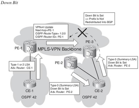
The down bit is a bit that is set in the Options field of an OSPF LSA type 3. It indicates the direction that the route has been advertised. If the OSPF route has been advertised from a PE router into an OSPF area, the down bit is set. Another PE router in the same area does not redistribute this route into iBGP of the MPLS VPN network if this bit is set. The PE router does not even
include the route in the SPF computation. As such, you can avoid a possible routing loop if the site is multihomed or if a backdoor link exists between OSPF sites.

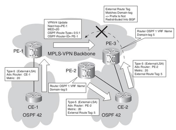
The domain tag (also known as the VPN route tag ) serves the same purpose as the down bit, but for OSPF external routes. You can set it manually on the PE routers with the command “domain-tag tag-value“ . If you set the domain tag to a particular value on a PE router, the tag value of the external OSPF route is set to that value. If another PE router that is connected to the same site or another site that is connected through a backdoor link receives this route and it matches the configured domain tag, the route is not redistributed into iBGP.

EIGRP
Redistributing the routes from BGP into EIGRP makes all the routes external EIGRP routes.
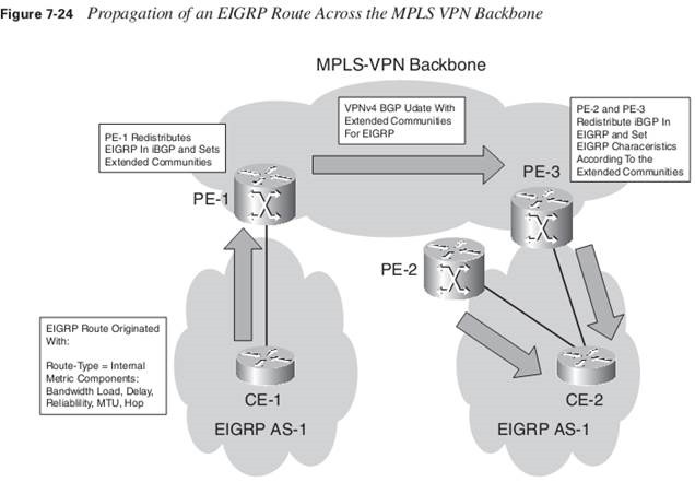

Nevertheless, the vpnv4 route that is learned from PE-1 is always preferred over the EIGRP route that is learned from the other PE in the same site. That is because the metric of the received routes is compared, and the lowest metric always wins. This is always the vpnv4 route from the remote PE router, if the cost of the EIGRP route is computed from reconstructing the metric components from the extended communities. This is why EIGRP does not need a down bit as OSPF does. The cost of traversing the MPLS VPN backbone is 0 for the EIGRP routes.
Because VPN customers usually use different EIGRP AS numbers (and the AS number has to match between EIGRP neighbors), the new EIGRP command autonomous-system as-number lets you specify the autonomous system number for the specified VRF.
EIGRP VRF Configuration Example
router eigrp 1
 no auto-summary
 !
 address-family ipv4 vrf cust-two
 redistribute static metric 64 2000 255 1 1500
 redistribute bgp 1 metric 300 40000 255 1 1500
 network 10.10.0.0 0.0.255.255
 no auto-summary
 autonomous-system 33
 exit-address-family
 !
 address-family ipv4 vrf cust-one
 redistribute bgp 1 metric 300 40000 255 1 1500
 network 10.0.0.0
 no auto-summary
 autonomous-system 42
 exit-address-family
Pre-Bestpath POI
The cost community in BGP is a nontransitive community that is passed to iBGP and confederation peers, but not beyond. It influences the BGP best path selection process by assigning cost values to specific routes.
The cost community is set with the set extcommunity cost command in a route map. You can set a cost community ID (0–255) and a cost value (0–4,294,967,295). The cost community ID indicates the preference of this BGP path versus the others. The lower the cost ID, the more preferred it is.
The point of insertion (POI) is the place in the BGP best path selection process where BGP considers the cost community. The pre- bestpath POI indicates that BGP is to consider the cost community before any of the regular BGP comparisons steps in the well- known BGP best path selection process. You can configure a pre-bestpath cost community by configuring the cost community with thepre-bestpath keyword in a route map. The cost community is of the form Cost:POI:ID:value .
It is the cost community with pre-bestpath that is set when EIGRP is redistributed into BGP. Without the cost community for EIGRP on the PE router, the PE router always prefers the locally sourced BGP route above the route learned from a BGP peer. In the case of having a backdoor link between two EIGRP sites, this means that the backdoor link is the preferred path. With the cost community for EIGRP, the backdoor link and the path learned from iBGP through the MPLS VPN backbone are compared. The path with the lowest EIGRP cost is the preferred path. Cost community for EIGRP over MPLS VPN is turned on automatically in the case of EIGRP as the PE-CE routing protocol, so you do not need to configure it. The POI is pre-bestpath. The cost community ID is either 128 or 129:128 for EIGRP internal routes and 129 for EIGRP external routes. Therefore, the EIGRP internal routes are always preferred over the EIGRP external routes. The value is the EIGRP composite metric value set on the PE router that redistributes the route into BGP. Routes that have a lower value are preferred over routes that have a greater value. If the cost community ID of the route and the value are the same, Cisco IOS prefers the EIGRP route over the BGP route on the PE router.
sydney# show ip bgp vpnv4 all 10.10.100.1
BGP routing table entry for 1:1:10.10.100.1/32, version 1259
Paths: (2 available, best #2, table cust-one)
  Advertised to update-groups:
     1
  Local
    10.200.254.2 (metric 3) from 10.200.254.2 (10.200.254.2)
      Origin incomplete, metric 256384000, localpref 100, valid, internal
     Extended Community: RT:1:1
        Cost:pre-bestpath:128:256384000 (default-1891099647) 0x8800:32768:0
        0x8801:42:256128000 0x8802:65281:256000 0x8803:65281:1500,
      mpls labels in/out 16/16
  Local
    10.10.4.2 from 0.0.0.0 (10.200.254.5)
      Origin incomplete, metric 2323456, localpref 100, weight 32768, valid, sourced, best
      Extended Community: SoO:10:10 RT:1:1
        Cost:pre-bestpath:128:2323456 (default-2145160191) 0x8800:32768:0
        0x8801:42:665600 0x8802:65282:1657856 0x8803:65281:1500,
      mpls labels in/out 16/nolabel
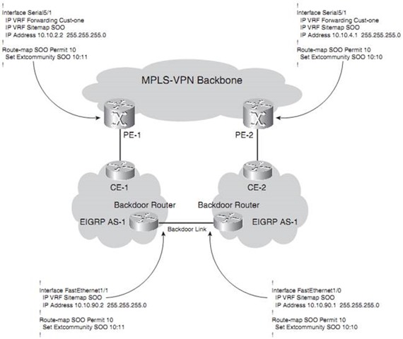
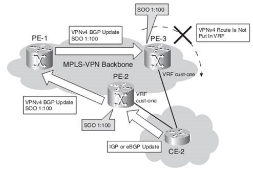
To help speed up the reconverging, you can use Site-of-Origin (SOO) for EIGRP. It can be defined on the PE routers on the VRF interfaces toward the CE routers and on the routers with a backdoor link. You need to configure ip vrf sitemap on the interface, setting the extended community SOO. This route map sets the SOO on the EIGRP route, either on the PE or on the backdoor link router. When the router receives a route across the interface with this route map configured and the SOO of the route matches the configured SOO, the router rejects the route. When the PE router receives a vpnv4 update with the SOO set, it extracts the SOO and adds it to the EIGRP route when it is reconstructed.

When no SOO for EIGRP is used anywhere, a count-to-infinity problem might exist.
With EIGRP, infinity is a hop count of 100 by default. You can lower the default maximum hop count of EIGRP by configuring the command metric maximum-hops hops.
PE-1# show ip eigrp vrf cust-one topology 10.10.100.3 255.255.255.255
IP-EIGRP (AS 42): Topology entry for 10.10.100.3/32
    State is Passive, Query origin flag is 1, 1 Successor(s), FD is 2297856
    Routing Descriptor Blocks:
    10.200.254.5, from VPNv4 Sourced, Send flag is 0x0
        Composite metric is (2297856/0), Route is Internal (VPNv4 Sourced)
        Vector metric:
        Minimum bandwidth is 1544 Kbit
        Total delay is 25000 microseconds
        Reliability is 255/255
        Load is 1/255
        Minimum MTU is 1500
        Hop count is 1
    Extended Community: SoO:10:10
Basic BGP Configuration as PE-CE Routing Protocol
router bgp 1
  neighbor 10.200.254.5 remote-as 1
  neighbor 10.200.254.5 update-source Loopback0
!
  address-family vpnv4
   neighbor 10.200.254.5 activate
   neighbor 10.200.254.5 send-community extended
   exit-address-family
!
  address-family ipv4 vrf cust-one
   redistribute connected
   neighbor 10.10.2.1 remote-as 65001
   neighbor 10.10.2.1 activate
  exit-address-family
If the customer has the same ASN at different sites, the CE routers drop the BGP routes.
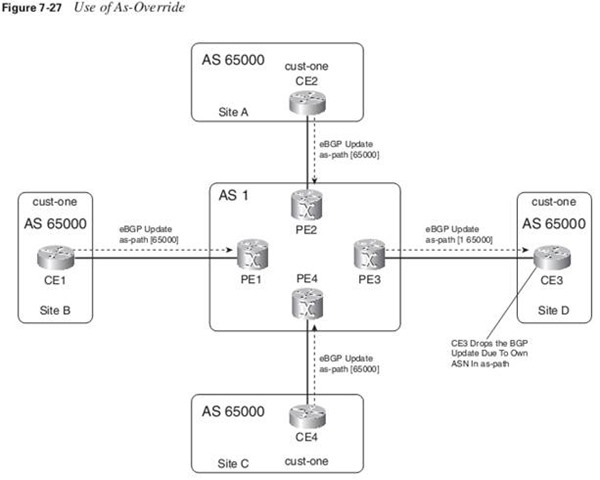

The command that you need to configure on the PE router to override the ASN is “neighbor ip-address as-override “. The safeguard against possible routing loops and suboptimal routing that comes from the as-path verification is now gone. Therefore, when using the as-override functionality, it is advisable to deploy the SOO feature for BGP.
neighbor allowas-in number: The number you can configure is from 1 to 10, specifying the number of times that the ASN is allowed in the as-path.
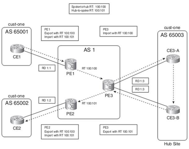
For Hub & Spoke MPLS-VPN Customers which do not need full-mesh connectivity, Two different RTs & Different RDs are needed.

BGP SSO
SOO uniquely identifies the site that originates a route. It is a BGP extended community that prevents routing loops or suboptimal routing, specifically when a backdoor is present between VPN sites. SOO provides loop prevention in networks with dual-homed sites (sites that are connected to two or more PE routers). You can use it when an IGP is the PE-CE routing protocol.
You can also use it when BGP is used between PE and CE, when the as-path loop prevention cannot be trusted anymore. This happens when BGP uses as-override or allowas-in.

SOO Route Map Configuration
route-map cust-one-soo permit 10
 set extcommunity soo 1:100
If the SOO is applied for BGP, the route map is configured on the BGP neighbor command.
You can also set the SOO for connected and static routes when they are redistributed into the IGP:
redistribute static route-map cust-one-soo
The tunnel interface on the PE router needs the command tunnel vrf vrf-name because the tunnel end point is not in the global routing space, but in the specified VRF. Because the tunnel does not have the ip vrf forwarding vrf-name command, it is in the global routing space.
Keyword global on the static VRF route: This ensures that traffic flowing from the CE router to the PE router via the VRF interface and being forwarded according to the static route is forwarded to the next hop in the global routing table.
ip route vrf cust-one 0.0.0.0 0.0.0.0 10.200.254.5 global
Because the traffic is no longer VPN-to-VPN but is forwarded in the global routing table, it has only one label in the MPLS VPN network.
Instead of traffic from each VPN site being forwarded directly to the Internet gateway router, it is possible to forward all the Internet traffic from the VRF sites to the CE router(s) of a central VRF site in a VPN. The advantage is that security features—such as firewall services—or other services—such as Network Address Translation (NAT)—are implemented only once and centrally in the central VRF site.
You can separate the departments by implementing VLANs on switches in the main site and mapping each VLAN to a VRF (sub) interface on the PE router. Instead of using a Layer 2 switch or one CE router per department, you can bring the VPN functionality to the CE router. For Multi-VRF CE, the separation into VRFs is used on the CE router as it is used on the PE router.
However, the CE does not need the other MPLS VPN functionality, such as labeling packets, Multiprotocol iBGP, and LDP. The interfaces toward the PE router are VRF interfaces. You need to configure the appropriate VRFs and VRF routing protocols on the Multi-VRF CE router.
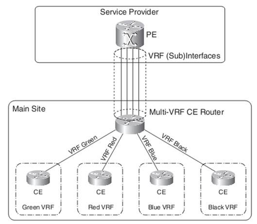

If the Multi-VRF CE router runs OSPF, you need to configure the command capability vrf-lite under the OSPF VRF process.
Investigating whether the down bit is set on summary LSAs:
- If it is, the route is discarded and not advertised further to the CE routers.
- Verifying whether the domain tag on the external OSPF routes matches the configured domain tag. If they match, the
external OSPF route is discarded.
For the Multi-VRF CE router to advertise the OSPF routes from the MPLS VPN backbone further down to the CE routers, you must disable these two checks under the OSPF process with the command capability vrf-lite.
PE Router Providing Management Access
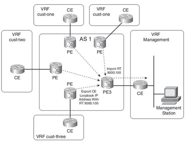

hostname sydney
!
ip vrf cust-one
 rd 1:1
 export map management
 route-target export 1:1
 route-target import 1:1
!
ip prefix-list CE-management-loopback seq 5 permit 10.10.100.3/32
!
route-map management permit 10
match ip address prefix-list CE-management-loopback
 set extcommunity rt  9000:100
!
!
hostname london
!
 ip vrf management
 rd 9000:1
 route-target export 9000:100
 route-target import 9000:100
london# show ip bgp vpnv4 rd 9000:1 10.10.100.3
BGP routing table entry for 9000:1:10.10.100.3/32, version 121
Paths: (1 available, best #1, table management)
  Advertised to update-groups:
     4
  65002, imported path from 1:1:10.10.100.3/32
    10.200.254.5 (metric 3) from 10.200.254.3 (194.68.129.9)
      Origin IGP, metric 0, localpref 100, valid, internal, best
      Extended Community: RT:9000:100
      Originator: 10.200.254.5, Cluster list: 194.68.129.9,
      mpls labels in/out 45/41
More and more service providers interconnect their MPLS VPN backbones. They can do this in two ways:
- Inter-Autonomous MPLS VPN
- CsC

