OSPF benefits
- Fast convergence
- Variable-length subnet masking (VLSM)
- Authentication
- Hierarchical segmentation
- Route summarization
- Aggregation
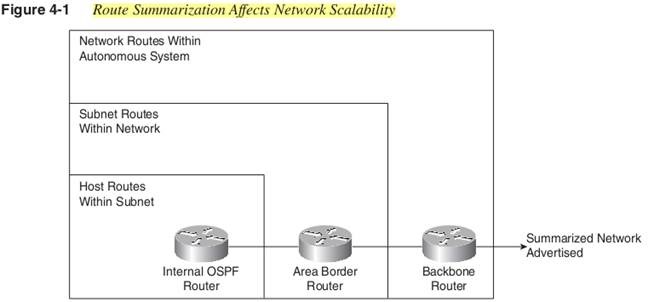
Routing Summarization is a major factor in the success of designing your network. To ensure that your network can scale properly, route summarization is the biggest factor against which to measure your success. Without summarization, you have a flat address design with specific route information for every subnet being transmitted across the network—a bad thing in large networks.

The six time-proven steps to designing a network are as follows:
- Analyze the requirements.
- Develop the network topology.
- Determine the addressing and naming conventions.
- Provision the hardware.
- Deploy protocol and Cisco IOS Software features.
- Implement, monitor, and maintain the network.
Consider the following issues when working through the network design process:
- Reliability: physical redundancy via the presence of backup routers or logical redundancy via extra circuits between key sites
- Latency: Investigate which applications are to be used.
- Amount of traffic: develop a baseline that can be used to project future growth. To do so, investigate the current network and determine the traffic levels and types.
- Multiple protocols on the WAN: by allowing only IP-based protocols on the network, you avoid the unique addressing and configuration issues that are related to other protocols. Therefore, you should not allow multiple non-IP protocols in a network—especially in the backbone.
- Support for remote offices and telecommuters
By default, OSPF support up to four equal-cost routes to a destination. When a failure to the destination is recognized, OSPF immediately switches to the remaining paths. OSPF can support a maximum of six equal-cost paths
The average time for OSPF to propagate LSAs and rerun the SPF algorithm is approximately 1 second. Then the SPF delay timer of 5 seconds must elapse. OSPF convergence can therefore be from 6 to 46 seconds, depending on the type of failure, SPF timer settings, size of the network, and size of the LSA database. The worst-case scenario is when a link fails but the destination is still reachable via an alternate route because the 40-second default dead timer needs to expire before the SPF is rerun.
Two common design topologies exist: meshed and hierarchical.
Full Meshed topology is not acceptable to the operation of OSPF. It does not correctly support the use of areas.
Hierarchical Topology
- Core layer: All these routers would interconnect and without host connections. The primary purpose of the core layer is to provide connectivity between other areas. In modern network design, the core layer can also be Gigabit Ethernet switches rather than routers.
- Distribution layer: A good location to begin implementing various network policies, such as security, Domain Name System (DNS), and so on.
Benefits of the OSPF hierarchical topology:
- Scalability—Networks can grow easily because functionality is localized, so additional sites can be added easily and quickly.
- Ease of implementation—This physical topology fits easily into OSPF’s logical hierarchy, making network implementation easier.
- Ease of troubleshooting —Because functionality is localized, it is easier to recognize problem locations and isolate them.
- Predictability —Because of the layered approach, the functionality of each layer is more predictable. This makes capacity planning and modeling easier.
- Protocol support—An underlying physical architecture is already in place. If you want to incorporate additional protocols, such as BGP, or if your organization acquires a network running a different protocol, you can easily add the protocol. For example, being able to connect an external network at the appropriate place in your network is enhanced with a hierarchical design.
- Manageability—The physical layout of the network lends itself to logical areas that make network management easier.
Always keep the backbone area as simple as possible by avoiding a complex mesh. Consider using a LAN solution for the backbone. The transit across the backbone is always one hop, latency is minimized, and the backbone is a simple design that converges quickly. Figure 4-5 illustrates a simple OSPF backbone design.
You need to keep users off the backbone because it is only a transit area. Because all other OSPF areas connect to the backbone, consider adding logical security. In OSPF, logical security can be in the form of route authentication.
Keep areas simple and stubby, with less than 100 routers (optimally 40 to 50) and have maximum summarization for ease of routing.
OSPF areas should also have a logical correlation to their placement, thus making the addressing and
subnetting much easier to handle. One of the benefits here is that you can grow the areas much higher.
Stub areas summarize all external LSAs into one default route, which provides a path to external routes for all traffic inside the stub area. The stub ABR forwards LSAs for inter-area routes but not external routes and
floods them to other area 0 routers. The stub ABR keeps the LSA database for the stub area with this additional information and the default external route.
An ASBR cannot be part of a stub area, and redistribution of routes from other protocols cannot take place in this area.
Totally stubby areas are a Cisco-specific feature
If an area is configured as totally stubby, only the default summary link is propagated into the area by the ABR interarea, and external LSAs are blocked at the ABR of a totally stubby area. AnASBR cannot be part of a totally stubby area, and redistribution of routes from other protocols cannot take place in this area.
The main difference between a stub area and a not-so-stubby area (NSSA) is that the NSSA allows the import of a limited number of external routes. You can configure areas that redistribute routing information from another protocol to the NSSA.
Note that by not using summarization, LSAs are propagated into the OSPF backbone and beyond, causing unnecessary network traffic and router overhead.
Type 1 and Type 2 LSAs are translated into Type 3 LSAs at the ABR, even if summarization is not turned on. (That is one unfortunate aspect of the terminology used in the RFC that calls this a Type 3 summary LSA.) Whenever an LSA is sent, all affected OSPF routers might potentially have to recompute their LSA database and routes using the SPF algorithm.
Routers in a remote area receive a Type 3 LSA every time a subnet changes in an area, but they can handle that change without a new SPF calculation. That is a hidden benefit of multi-area OSPF: Routers in remote areas can process changes without a full SPF calculation.
Only summary-link LSAs propagate into the backbone (area 0)
IP addresses in an OSPF network should be grouped by area, and you can expect to see areas with some or all of the following characteristics:
- Major network number(s)
- Fixed subnet mask(s)
- Random combination of networks, subnets, and host addresses
The allocation should be in the form of contiguous blocks that are adjacent so that OSPF LSAs can easily represent the address space.
Allocation of IP addresses should be done in powers of 2 so that these “blocks” can be represented by a single summary link advertisement. Through the use of the area range command, you can summarize large contiguous blocks of addresses. To minimize the number of blocks, make them as large as possible.
To differentiate two areas, split 1 bit. To differentiate 16 areas, split 4 bits.
Discontiguous subnets are supported by OSPF because subnets masks are part of the link-state database.
In the OSPF specification, MD5 is the only cryptographic algorithm that has been completely specified.
However, each router that is directly connected to each other must have the same key for communication to take place.
When routes are redistributed between major networks, no subnet information is required to be shared. Instead, summarization should be applied at major network boundaries.
Operationally, OSPF networks should be designed so that areas do not need to be split to accommodate predicted and unpredicted growth. Networks will most likely not shrink in size, so plan accordingly. Specifically, reserve IP address space to permit the addition of new routers and areas.
All routers keep a copy of the area’s link-state database (LSDB). If a router is in more than one area, such as an ABR, the router has one LSDB for each area. As your network grows, its size eventually reaches a point where the database becomes too large, resulting in routing inefficiencies because the router does not have the resources to handle normal routing activities.
The larger the OSPF area, the more LSAs are flooded throughout the network whenever there is a topology change.
However, too many LSAs causing slow SPF calculations is quite common–especially LSAs from external routes being flooded across the entire AS.
Most important task is to determine which routers and links are to be included in the backbone (area 0) and which are to be included in each area.
Experience has shown that 40 to 50 routers per area is the optimal upper limit for OSPF in the majority of networks.
The number of calculations that must be performed by the router, given that n is the number of link-state packets (LSPs), is proportional to n log n. As a result, the larger the area, the greater the likelihood for performance problems associated with OSPF routing recalculation, and the more unstable the area becomes.
ABRs keep a copy of the database for all areas that they service.
The ideal design is to have each ABR connected to two areas only—the backbone and another area
A router must run the link-state algorithm for each link-state change that occurs for every area in which the router resides.
OSPF floods all link-state changes to all routers in an area. Routers with many neighbors have the most work to do when link-state changes occur.
To improve performance, avoid having a single router be the DR on more than one segment.
If OSPF defaults to the DR selection based on the highest router ID (loopback interface or highest active IP address on an interface), one router might accidentally become a DR over all segments to which it connects.
- Do not allow a router to “accidentally” become the DR.
- Plan which router is to be the DR in an area.
- By default, all Cisco routers have a priority of 1, thus forcing the use of the router ID (RID) as the deciding factor.
Adding a router with a high priority to a segment does not cause a new election.
- A router with a router priority set to 0 is ineligible to become the DR or BDR.
It’s a good idea to set OSPF priority to zero on firewalls that happen to speak OSPF, or your DR might become a firewall that is routing packets in software, rather than ASICs
From an NBMA network perspective, this is also something to consider because you would not want your expensive WAN links full of unnecessary overhead.
In some cases, a carefully laid out point-to-point or point-to-multipoint network can work better than multipoint networks, which must deal with LSA and DR issues.
- A router has a separate LSDB for each area to which it belongs.
- All routers belonging to the same area have an identical LSDB.
- A router performs separate SPF calculations on associated LSDBs for each area.
- LSA flooding occurs only within the area that is sending the advertisement (that is, experiencing the topology change). Remember that Type 1–4 and Type 7 LSAs are flooded within an area, and Type 5 LSAs are flooded throughout the OSPF domain, except for stub and NSSA areas.
LSDB contains the following different LSAs
- Router link advertisements
- Network link advertisements
- Summary link advertisements (IP network and ASBR)
- Autonomous system (AS) external advertisements (nonstub areas only)
- Opaque LSAs, if implemented
An OSPF router stores all the link states for all the areas that it is in.
In addition to storing the state of each link within an area, the LSDB stores summary and external routes. Careful use of route summarization techniques and the creation of stub areas can substantially reduce router memory use. Therefore, if memory issues become a concern, consider using stub areas because doing so reduces the amount of routes.
Memory issues usually arise when too many external routes are injected into the OSPF domain.
- Each entry in the routing table consumes 200 to 280 bytes plus 44 bytes per link.
- Each LSA consumes 100 bytes worth of overhead plus the size of the actual LSA, possibly another 60 to 100 bytes. (For router links, this depends on the number of interfaces on the router.) These amounts should be added to memory already used by other processes and by the Cisco IOS Software.
An OSPF router uses CPU cycles whenever a link-state change occurs. This is because Cisco IOS Software is run in the router’s flash memory, and every time a decision is required, the CPU must process it.
OSPF sends partial LSA updates when a link-state change occurs. The updates are flooded to all routers in the area.
For OSPF to operate properly, all routers within an area must have the same database. As a result, it is not possible to use route filters in an OSPF network to provide security because OSPF exchanges route information through the use of LSAs, not routes.
All routers within an area must agree on the value of the authentication field (that is, the password)
If a particular location within your network is densely connected, create an area specifically for the routers at that location. This enables OSPF to better handle a large, dense cluster of routers, and it enables more efficient management and routing.
By segmenting your network into smaller or multiple areas, you can isolate unstable links and deliver more reliable overall service.
Basically, all routers in the backbone should be directly connected to other backbone routers. This does not mean that all routers must share a common network media (such as Ethernet).
All of these commands and their associated values generally default to good values. If you are considering changing these defaults, it is good practice to change them in all routers in an area, or your routers might have trouble communicating.
ip ospf retransmission-interval {default = 5 seconds} : An LSA retransmission automatically occurs while the
transmitting router is waiting for an acknowledgment from the receiving router. Remember if you alter this to allow for round-trip time and delays between routers.
ip ospf transmit-delay {default = 1 second}
ip ospf cost: The cost that you set on an interface via this command is retransmitted in the router LSA (Type 1).
100-Mbps Fast Ethernet default cost is 1
Standard, or non-stub, OSPF areas carry a default route, static routes, intra-area routes, and external routes.
- An area must be a standard area when it contains a router that uses both OSPF and any other protocol
- An area must also be a standard area when a virtual link is configured across the area. This is because the various types of stub areas are not allowed to have virtual links in them.
OSPF backbone is the part of the OSPF network that acts as the primary path for traffic that is destined to other areas or networks.
There should never be more than three tiers with a maximum of six router hops across the farthest points of the network.
Understand that area 0 is a transit area, not a destination for traffic.
The backbone must be at the center of all other areas
Every router in the backbone needs to recompute its routes after every link-state change.
All routers in the backbone should be directly connected to other backbone routers.
Stub area carries a default route and inter-area routes but does not carry external routes.
A default route 0.0.0.0/0 is advertised into the stub area
- No ASBRs can be within a stub area.
- No virtual links are allowed to transit the area.
area area-id stub must be applied to all routers in the area being designated as a stub.
Normal stub areas block only external routes; however, they do allow summary routes.
LSA Types 1 through 4 are allowed and 5 through 7 are blocked.
If the cost is not set using the area area-id default-cost cost command, a cost of 1 is advertised by the ABR.
The only routes that appear are the intra-area routes (O) and the default route 0.0.0.0. The external and inter-area routes have been blocked. The cost of the default route is now 74 (64 for a T1 line + 10 advertised by RTC). No configuration is needed on RTE in this case. The area is already stub, and the no-summary command does not affect the Hello packet as the stub command does.
The totally stubby area (TSA) feature is Cisco proprietary and not supported in the official OSPF standard. But as long as the ABR connected to the TSA is a Cisco router, the rest of the routers in the TSA are not affected.
A TSA blocks external routes and summary routes from entering the area. This leaves the default route and intra-area routes (routes in the TSA) as the only types being advertised throughout the area.
LSA, Type 7, is responsible for carrying external route information
An NSSA does not flood Type 5 external LSAs from the core into the NSSA, but as a hybrid stub area, an NSSA has the capability to import AS external routes in a limited fashion within the area, which is what makes it an NSSA.
Consider an ASBR connected to a network running RIP. This router is also configured as part of an NSSA. The router redistributes the routes learned from RIP into an OSPF Type 7 LSA for transmission into the NSSA. The NSSA ABR sees these advertisements and wants to forward them onto
area 0 for distribution throughout the network. The ABR then redistributes the Type 7 LSAs into Type 5 LSAs.
Use an NSSA when the area lies between an ASBR and ABR, and where the ASBR connects to a different routing protocol and the ABR connects to OSPF’s area 0.
- You can set a Type 7 default route that can be used to reach external destinations. When configured, the router generates a Type 7 default into the NSSA by the NSSA ABR.
- Every router within the same area must agree that the area is NSSA; otherwise, the routers cannot communicate with each other.
area area-id nssa [no-redistribution] [ default-information-originate]
On the ABR, to control summarization and filtering of a Type 7 LSA into a Type 5 LSA during the translation
router(config-router)# summary address prefix mask [not advertise ] [ tag tag ]
Virtual links are not a true tunnel in the sense that one protocol is encapsulated by another.
Accepted network design theory considers the use of virtual links a result of a poorly designed backbone or network.
In other instances, virtual links are added for logical redundancy in case a router failure causes the backbone to be split into two. For whatever reason, a virtual link can be configured between separate ABRs that touch area 0 from each side and have a common area (see Figure 4-29).
- Virtual links can only be configured on ABRs.
- Virtual links cannot run across stub areas.
- OSPF treats two routers joined by a virtual link as if they were connected by an unnumbered point-to-point network.
- Virtual links cannot be configured on unnumbered links.
Note that a new area exists that cannot be physically connected to area 0, so as a temporary solution, a virtual link is configured while waiting for the delivery of the physical circuit that is on order.
|
Neo#show ip ospf virtual-links Virtual Link OSPF_VL1 to router 100.0.29.1 is up Run as demand circuit DoNotAge LSA allowed. Transit area 201, via interface FastEthernet0/1, Cost of using 65 Transmit Delay is 1 sec, State POINT_TO_POINT, Timer intervals configured, Hello 10, Dead 40, Wait 40, Retransmit 5 Hello due in 00:00:01 Adjacency State FULL (Hello suppressed) Index 2/3, retransmission queue length 0, number of retransmission 1 First 0x0(0)/0x0(0) Next 0x0(0)/0x0(0) Last retransmission scan length is 1, maximum is 1 Last retransmission scan time is 0 msec, maximum is 0 msec |
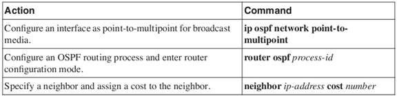
- On point-to-multipoint nonbroadcast networks, you now use the “neighbor” command to identify neighbors. Assigning a cost to a neighbor is optional.
With this feature, you can configure a separate cost to each neighbor. This feature applies to point-to-multipoint interfaces only.
Steps to Assigning a Cost to Each Neighbor in Point-to-Multipoint Broadcast Networks

You can configure the delay time between when OSPF receives a topology change and when it starts an SPF calculation. You can also configure the hold time between two consecutive SPF calculations. To do this, use the following command in router configuration mode:
timers spf spf-delay spf-holdtime
Split horizon dictates that a routing update received on an interface cannot be retransmitted out onto the same interface. This rule holds even if the routing update was received on one Frame Relay permanent virtual circuit (PVC) and was destined to retransmit out onto another Frame Relay PVC.
Cisco serial interfaces are multipoint interfaces by default
The Hello and dead timers vary for different network types as follows:
R is Received and C is Configured
|
Apoc# debug ip OSPF events *Mar 1 01:38:54.259: OSPF: Rcv hello from 172.16.16.1 area 2 from Serial0 172.16.16.1 *Mar 1 01:38:54.263: OSPF: Mismatched hello parameters from 172.16.16.1 *Mar 1 01:38:54.263: Dead R 40 C 120, Hello R 10 C 30 Mask R 255.255.255.252 C 255.255.255.252 *Mar 1 01:39:01.991: OSPF: Rcv hello from 51.0.19.1 area 51 from Serial1.1 51.0.0.3 *Mar 1 01:39:01.991: OSPF: End of hello processing *Mar 1 01:39:04.183: OSPF: Rcv hello from 172.16.16.1 area 2 from Serial0 172.16.16.1 *Mar 1 01:39:04.187: OSPF: Mismatched hello parameters from 172.16.16.1 *Mar 1 01:39:04.191: Dead R 40 C 120, Hello R 10 C 30 Mask R 255.255.255.252 C 255.255.255.252 *Mar 1 01:39:05.327: OSPF: Rcv hello from 51.0.29.1 area 51 from Serial1.1 51.0.0.4 *Mar 1 01:39:05.331: OSPF: End of hello processing *Mar 1 01:39:14.199: OSPF: Rcv hello from 172.16.16.1 area 2 from Serial0 172.16.16.1 *Mar 1 01:39:14.203: OSPF: Mismatched hello parameters from 172.16.16.1 *Mar 1 01:39:14.207: Dead R 40 C 120, Hello R 10 C 30 Mask R 255.255.255.252 C 255.255.255.252 *Mar 1 01:39:24.199: OSPF: Rcv hello from 172.16.16.1 area 2 from Serial0 172.16.16.1 *Mar 1 01:39:24.203: OSPF: Mismatched hello parameters from 172.16.16.1 *Mar 1 01:39:24.207: Dead R 40 C 120, Hello R 10 C 30 Mask R 255.255.255.252 C 255.255.255.252 Apoc#u all All possible debugging has been turned off Apoc#conf t Enter configuration commands, one per line. End with CNTL/Z. Apoc(config)# int s0 Apoc(config-if)# ip ospf network ? broadcast Specify OSPF broadcast multi-access network non-broadcast Specify OSPF NBMA network point-to-multipoint Specify OSPF point-to-multipoint network point-to-point Specify OSPF point-to-point network Apoc(config-if)# ip ospf network point-to-point Apoc(config-if)# ^Z Apoc# *Mar 1 01:43:46.831: %SYS-5-CONFIG_I: Configured from console by console Apoc#debug ip ospf events OSPF events debugging is on *Mar 1 01:44:02.047: OSPF: Rcv hello from 51.0.19.1 area 51 from Serial1.1 51.0.0.3 *Mar 1 01:44:02.051: OSPF: End of hello processing *Mar 1 01:44:04.687: OSPF: Rcv hello from 172.16.16.1 area 2 from Serial0 172.16.16.1 *Mar 1 01:44:04.691: OSPF: End of hello processing *Mar 1 01:44:05.287: OSPF: Rcv hello from 51.0.29.1 area 51 from Serial1.1 51.0.0.4 *Mar 1 01:44:05.291: OSPF: End of hello processing *Mar 1 01:44:10.095: OSPF: Rcv hello from 172.16.16.1 area 0 from OSPF_VL0 172.16.16.1 *Mar 1 01:44:10.387: OSPF: Interface OSPF_VL0 going Up *Mar 1 01:44:14.691: OSPF: Rcv hello from 172.16.16.1 area 2 from Serial0 172.16.16.1 *Mar 1 01:44:14.695: OSPF: End of hello processing |
Also, on any point-to-multipoint interface (broadcast or not), Cisco IOS Software assumed that the cost to each neighbor was equal.
DLCI address space—Approximately 1000 DLCIs
No static frame-relay map statements were configured because Inverse ARP (Address Resolution Protocol) takes care of the DLCI-to-IP resolution and mapping.
You cannot ping your own IP address on a multipoint Frame Relay interface because Frame Relay multipoint (sub)interfaces are nonbroadcast (unlike Ethernet and point-to-point interfaces [HDLC] and Frame Relay point-to-point sub-interfaces). Furthermore, you cannot ping from one spoke router to another spoke router in a hub-and-spoke configuration because there is no mapping for your own IP address (and none was learned via Inverse ARP). However, if you configure a static map (frame-relay map) for your own IP address (or one for the remote spoke) to use the local DLCI, you can ping yourself.
There is no DR or BDR, which is normal and expected behavior for an NBMA media.
Optimum solution for OSPF over Frame Relay or other NBMA network is point-to-point subinterfaces.
The initial step of DR/BDR election is not required because only two routers exist on point-to-point networks, resulting in quick adjacency formation upon startup.
router(config-if)# ip ospf authentication-key BLAHBLAH
router(config-router)# area 64 authentication
The keyword metric-type 1 makes redistributed IGRP routes external Type 1. This allows the OSPF spoke routers to add individual link costs to calculate OSPF metrics.

