
Being involved in different Data Center design projects requires you knowing how to interconnect Data Centers. Below you’ll find my notes from Cisco Data Center Design & Implementation Guide, System Release 1.0.
DCI Business Drivers: 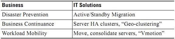

- Microsoft MSCS
- Veritas Cluster Server (Local)
- Solaris Sun Cluster Enterprise
- VMware Cluster (Local)
- VMware VMotion
- Oracle Real Application Cluster (RAC)
- IBM HACMP
- EMS/Legato Automated Availability Manager
- NetApp Metro Cluster
- HP Metrocluster
Active/Standby Migration, Move/Consolidate Servers
- VMware Site Recovery Manager (SRM)
- Microsoft Server 2008 Layer 3 Clustering
- VMware Vmotion
The applications above drive the business and operation requirement for extending the Layer 2 domain across geographically dispersed data centers. Extending Layer 2 domains across data centers present challenges including, but not limited to:
- Spanning tree isolation across data centers
- Achieving high availability
- Full utilization of cross sectional bandwidth across the Layer 2 domain
- Network loop avoidance, given redundant links and devices without spanning tree
DCI Connectivity Overview
- Layer 2 Extensions: Provide a single Layer 2 domain across data centers. The data center applications are often legacy or use embedded IP addressing that drives Layer 2 expansion across data centers.
- Layer 3 Extensions: Provide routed connectivity between data centers used for segmentation/virtualization and file server backup applications. This may be Layer 3VPN-based connectivity, and may require bandwidth and QoS considerations.
- SAN Extensions: Storing and replicating data for business continuity, disaster recovery, and/or regulatory compliance.
Design Goals
All DCI designs should meet the basic guidelines and requirements set forth in this DIG. DCI compatible platforms meet and support the following requirements:
- Layer 2 transport mechanism (VSS, vPC)
- High Availability (HA)
- Spanning Tree Isolation
- Loop avoidance
- Multi Path load balancing
- End-to-End convergence of 2-4 seconds
- Aggregating 2-4 10GE/GE and forwarding at least 1-2 10Gbps across the WAN
- Providing basic queuing
- Interconnect traffic encryption
Transport Options
Data centers may be interconnected over the following DCI-classified transport options:
- Dark Fiber (Optical)
- MPLS
- IP
VLANs are often divided into odd and even sections and forwarded via the resilient network to achieve HA, scalability and efficient cross-section Layer 2 link utilization.
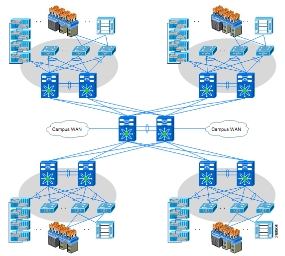
The Core Layer can be collapsed with a WAN Layer in a data center network. In some designs a customer may choose to collapse the data center Core/WAN and Aggregation Layers, which not only raises design issues but at times operational issues as well.
By configuring all links connecting to the network core as point-to-point Layer 3 connections, rapid convergence around any link failure is provided, and the control plane of the core switches is not exposed to broadcast traffic from end node devices, or required to participate in Spanning Tree Protocol (STP) for Layer 2 network loop prevention.
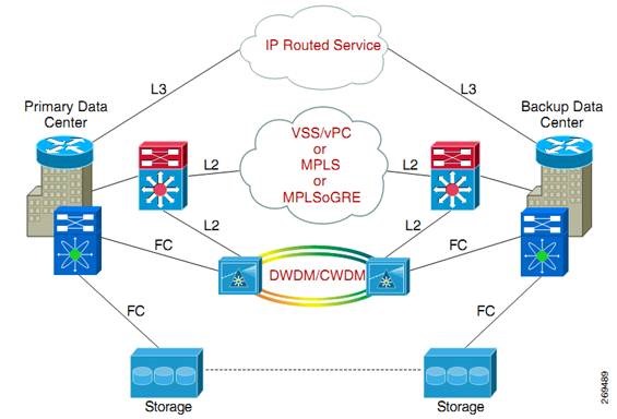
Small Simple DC Network

Large DC Network with Collapsed Core Layer

Large DC Network with Additional Core Layer

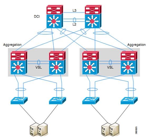
The Aggregation Layer is configured with Virtual Switching System (VSS), virtual Port Channel (vPC), or Non-VSS dual Catalyst 6500 Series switches in the DCI topology.
The Aggregation Layer also acts as the root of the local STP domain. A key requirement of a DCI solution is the need to isolate spanning tree domains and keep them local to each data center. This is achieved by filtering spanning-tree Bridge Protocol Data Units (BPDU’s) on the MEC link from local data centers going to the remote data center.
The Core switches are configured with BGP to interact with the WAN, and HSRP is configured to provide redundancy.
DC Interconnect Layer
The DCI Layer provides the following options for the Layer 2 extension service:
- The DCI Layer could be part of the WAN router to be covered in Release 2.0 for MPLS deployments.
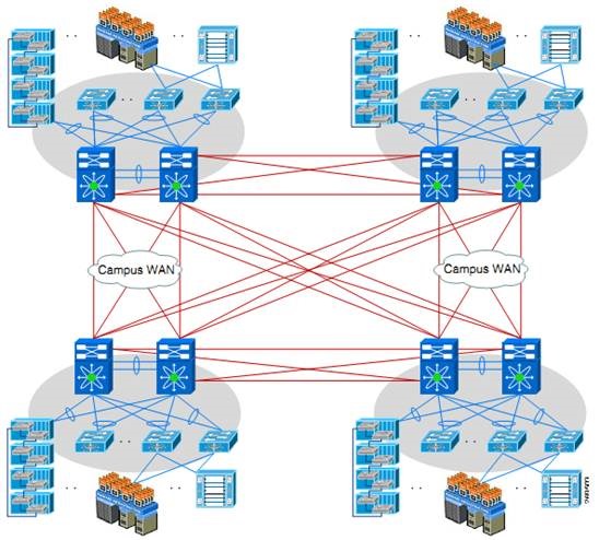
- In large-scale data centers where multiple aggregation blocks are built out, as shown in Figure 1-5, a separate set of redundantly configured devices form a separate DCI Layer, which can aggregate multiple pairs of Aggregation Layer switches, as was tested in the DCI Release 1.0.
The purpose of this design is to:- Reduce the number of links that need to go across the WAN.
- Allow Layer 2 connectivity not only across data centers but also within aggregation blocks in the same site.
- For smaller data centers that consist of a single set of aggregation switches, as shown in Figure 1-6, it might be hard to justify adding additional layer to extend the Layer 2 domain. In such scenarios, the Aggregation switches themselves could also be used to extend the Layer 2 domain and act as a DCI Layer switch (an assumption is made here that the Aggregation switches are VSS). The DCI Release 1.0 uses MEC to connect two data centers, ensuring both links are forwarding and optimally utilized under normal conditions.
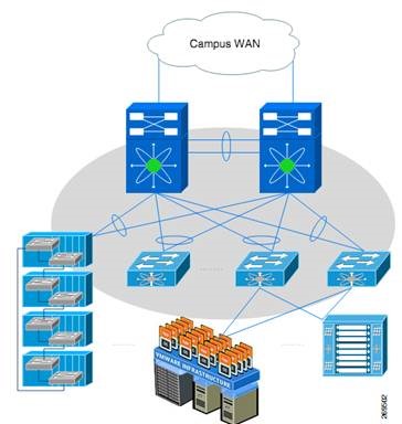
Large DC with Multiple Aggregation Blocks

Small DC with Aggregation

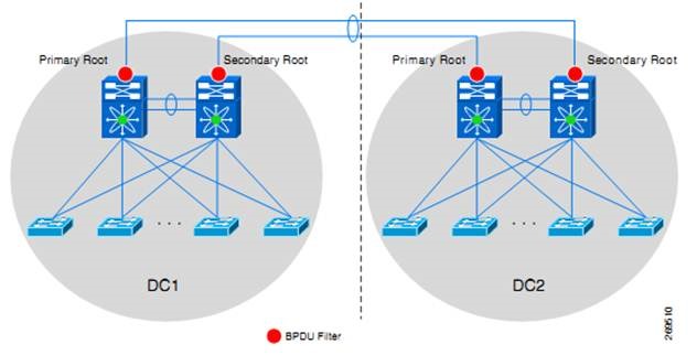
The reasoning behind isolating the STP domains is to:
- Assure that an STP loop event in one site doesn’t affect the other sites.
- Assure an optimal placement for the STP primary and secondary root can be achieved in each datacenter.
However, in active/active or active/standby data centers, where the same subnet is extended across multiple data centers summarization of all routes may not be possible and hence more specific routes even host routes can be used to avoid sub-optimal or asymmetric routing as it can cause severe issues with TCP congestion flow mechanisms.
Layer 2 Considerations
Building Layer 2 extensions for DCI is essential and critical in design. While extending Layer 2 is the primary focus of this section, routing plays an important role between data centers as well. Not all traffic has a requirement to be passed within the same VLAN (bridged). Most application or server-to-server traffic is able to traverse Layer 3 hops. To provide Layer 3 connectivity one additional VLAN is provisioned between the sites. This VLAN is a pure “transit VLAN” which connects all aggregation layer switches or core routers into a single subnet to establish a routing adjacency. This way traffic that needs to be routed between data centers can make use of the bandwidth available on the DCI link.
Adjacency Using VLANs
The requirement for clustered applications, legacy non-IP implementations as well as virtual machine mobility, dictate that some VLANs extend between data centers. It is important to understand that Layer 2 expansion should be carefully performed, and applied only to VLANs that necessitate such connectivity. The VLAN number space between data centers must be coordinated. If VLAN spaces are overlapping and can’t be reassigned or realigned, VLAN translation may be considered and is typically configured in the Aggregation or DCI Layers.
BPDU Filtering Impact

DCI Network Components


DCI Topologies
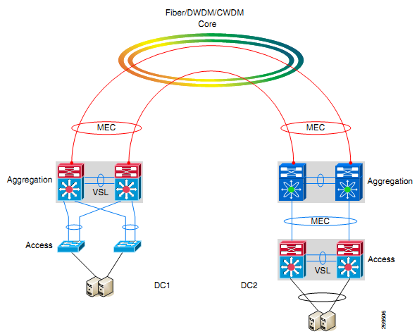
DCI Fiber, DWDM, and CWDM Core Topology


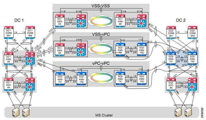
VSS-VSS 2-Site Test Topology

VSS-vPC 2-Site Test Topology

2 Sites vPC-vPC Case Study

Use Cases
For each of these use cases, as they were tested, certain levels of scale were built into the topologies in order to get closer to real-world deployment scenarios. The following list provides the scale numbers that may be of interest:
- 500 Layer 2 VLANs (see note below)
- 100 VLAN SVIs
- 10,000 client-to-server flows
- 20 Gbps traffic flows between data centers
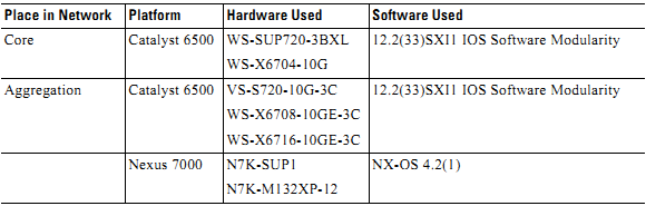
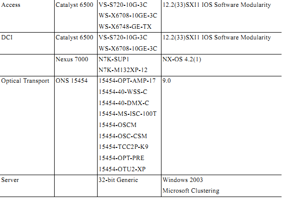
DCI Hardware/Software Coverage


Dual-Site Test Topologies
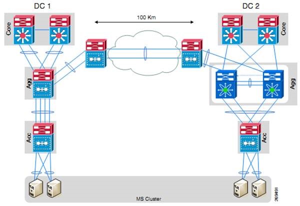
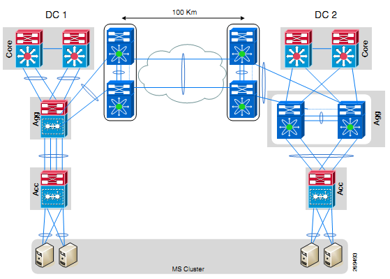
As indicated above, there were four use cases covered with two data centers connected at Layer 2. As in all use cases, these two sites are connected by DWDM running over dark fiber. The ONS-15454 platform was leveraged to provide the optical connections between the data centers. Two 10 Gbps protected links were deployed to provide a 20 Gbps aggregate bandwidth between the data centers. For the most part, the optical transport was a “black box” as far as the testing was concerned, with only a small handful of tests taking place in that domain. Fiber spools were deployed in the test topology to provide a real fiber distance of 100 kilometers between the two data centers.
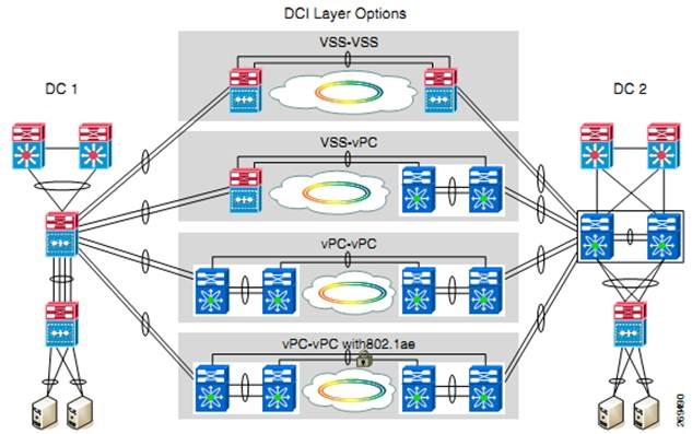
DCI Layer options for dual-site deployments are called out in the Figure 2-8 and correspond respectively to the first four use cases listed above. Each of these deployment options is covered in more detail in the material below:
Dual-Site Use Cases Summary View

Core Layer
In each data center, the Core Layer is composed of a pair of Catalyst 6500s using the following hardware (per switch):
- WS-SUP720-3BXL
- WS-X6704-10GE
Supervisor 720-3BXL was used to accommodate the larger routing tables that are commonly seen at this position in the network. The links connecting the Core Layer to the Aggregation Layer are 10 Gigabit Ethernet (GE) Layer 3 links. A single link of the same speed is connecting the Core switches to each other. There are 10 Gigabit Ethernet links connecting the Core switches to a traffic generator, also. The traffic profiles are discussed in more detail in another section below.
As illustrated in the diagram, there are two 10 GE links connecting each Core Layer switch to the Aggregation Layer. With VSS being employed at the Aggregation Layer in Data Center 1, this pair of switches is presented, logically, as a single switch. The two links from each Core switch, therefore, are bundled into a single logical link, using EtherChannel technologies.
All of the links emanating from the Core Layer are Layer 3 links. The links going north towards the Campus core (not pictured) are running BGP.
BGP-to-OSPF redistribution of those routes was done in these Core Layer switches.
The links both between the Core Layer switches and from them to the Aggregation Layer switches were running OSPF, and all links were in Area 0.
Aggregation Layer
As mentioned above, the Aggregation Layers in the respective data centers, while serving the same function, are different in that they are built on different switching platforms. The Aggregation Layer in Data Center 1 is built on the Catalyst 6500 platform using the VSS technology to present the pair of physical switches as a single logical entity.
The hardware needed for this, and deployed in these switches, includes (per switch):
- VS-S720-10G-3C
- WS-X6708-10G-3C
Each of the inter-switch links (ISLs) connecting the Aggregation Layer switches to neighbor switches are 10 GE. The Multichassis EtherChannel (MEC) technology is used to bundle the links coming from the different physical chassis as a single logical EtherChannel link.
Not shown in the topology diagram is the Virtual Switch Link (VSL) necessary for VSS to operate. The VSL is composed of two 10 GE links bundled together using EtherChannel technology. Two links are used for two main reasons:
- To provide redundancy for the critical VSS heartbeat messages and control plane messages sent between the two physical chassis.
- To provide an aggregate bandwidth (20 Gbps here) large enough to accommodate data plane traffic that may need to pass between one chassis and the other, on its way to the destination. To provide further redundancy, the VSL links are split between the supervisor 10 GE uplink and one of the 10 GE line cards in the chassis.
In Data Center 2, the hardware used in each Nexus 7000 chassis was the same:
- N7K-SUP1
- N7K-M132XP-12
All the ISLs connecting these Aggregation Layer switches to other devices were 10 GE from the 32-port 10GE line cards. As with VSS and the VSL, there is a EtherChannel connecting the two Nexus 7000 chassis in the vPC pair called the Peer Link. For redundancy, the two links in this bundle are split across multiple line cards. For further protection from an accidental dual active state, there is another link between the two chassis called the Peer Keepalive Link (PKL). This link does not directly attach the two chassis. Rather, it is a separate Layer 3 connection.
Aggregation Layer demarcates the boundary between Layer 2 and Layer 3. In the tested topologies, the Layer 3 links, running OSPF as the IGP, connect up to the Core Layer. The remaining links in the Aggregation Layer are Layer 2.
In those data centers where the Aggregation Layer was made up of two Catalyst 6500 switches, the Layer 2 link between these switches formed the VSL that helped to maintain the integrity of the VSS system.
In the data center where the Aggregation Layer was made up of two Nexus 7000 switches, the Layer 2 link between these two switches formed the vPC Peer Link necessary for the vPC feature. For the VSL link that connected the two Catalyst 6500 switches in the VSS system, Port Aggregation Protocol (PAgP), in Desirable mode, was used to bundle the two links into a single port channel. For the Peer Keepalive link connecting the Nexus 7000 switches, Link Aggregation Control Protocol (LACP) was used, with the ports in Active mode.
Due to the virtual nature of either two Catalyst 6500 or two Nexus 7000 switches combined using either VSS or vPC, the single links that connect the Aggregation Layer to the Access Layer are bundled into one logical Multichassis EtherChannel (MEC). This is configured just as a normal EtherChannel, using either PAgP with the member interfaces in desirable mode (in the case of two Catalyst 6500s being connected) or Link Aggregation Control Protocol (LACP) with the members in active mode (in the case of a Catalyst 6500 connecting to a Nexus 7000).
Aside from OSPF, the other Layer 3 protocol running at the Aggregation Layer was Hot Standby Router Protocol (HSRP) which provided gateway redundancy to hosts in a given subnet. Of the 500 Layer 2 VLANs that were configured in the Layer 2 domain that was extended between sites in the 2-site or 3-site test topologies, 100 were mapped to Layer 3 interfaces, or SVIs. These SVIs were all configured with HSRP, sharing a common group across all data centers in a given topology.
Since multiple devices were participating in a single HSRP group, the configured HSRP priorities were manipulated such that the active HSRP router was the Aggregation Layer VSS device in DC 1. One of the vPC devices in the Aggregation Layer of DC 2 was the standby HSRP router for each HSRP group while the second Nexus 7000 remains in HSRP Listening state. The configuration is the same with the third site present in the topology, with the VSS device in that third site also waiting in Listening state.
The Layer 2 VLANs are trunked from the Aggregation Layer switches to the Access Layer switches using 802.1q VLAN tagging. The trunking mode is set to on. For the entire Layer 2 domain, the VTP mode is configured as transparent.
Rapid spanning-tree protocol (rPVST+) is configured on all Layer 2 devices, including at the Aggregation Layer. Since the Aggregation, Access and DCI Layers are all either VSS or vPC, though, spanning-tree is not blocking any ports as there are no Layer 2 loops to prevent. The STP Root switch was configured as the VSS switch in DC 1, while the Secondary Root switch was the first vPC switch in DC 2.
Fast Hello was selected as the preferred VSS Dual Active detection mechanism. This is because Fast Hello has been identified as the most reliable and robust Dual Active detection mechanism. VSS chassis and VSL link failure events with the Fast Hello mechanism enabled yielded sub-second convergence times for failure and full recovery.
VSS-to-VSS DC Interconnect
Data center inter connectivity is accomplished by a pair of Catalyst 6500 switches using VSS at the DCI Layer of either data center. The MEC between them is built across the optical transport (DWDM in this case) so that a full 20 Gbps of bandwidth exists to connect the two data centers.
DCI Layer
The Catalyst 6500s deployed at the DCI Layer in each of the two data centers have similar hardware deployments, as listed below:
- VS-S720-10G-3C
- WS-X6708-10G-3C
As mentioned, the links between the VSS pairs in each data center are 10 Gigabit Ethernet, and bundled into a MEC. Likewise, the links from the DCI Layer VSS switches to the Aggregation Layer VSS switches are also 10 GE and bundled into a MEC. As per best practices, the respective VSLs are built with dual-10 GE links distributed between the supervisor and one line card.
In the VSS-to-VSS test topology, the VSS devices in either data center were strictly Layer 2. These devices connected to each other across the DWDM ring in order to extend the Layer 2 domain from one data center to the other. From the perspective of most Layer 2 protocols, then, the configuration at the DCI Layer was the same as at either the Aggregation or Access Layers.
There are some important configurations to point out at the DCI Layer, though, and these will apply to all of the 2-site topologies that were tested.
Outside of the test cases used to validate the system fault isolation capabilities, the spanning-tree domain extended between the two data centers, along with the 500 VLANs. That means that there was a single STP root for both data centers (it was DC2-AGG-7K-1 in all 2-site use cases) and a single STP secondary root (was DC1-AGG-6K).
For the fault isolation test cases, the larger STP domain was split into two through the use of BPDU Filtering. For this test case, a Layer 2 loop, and subsequent broadcast storm, was introduced in one data center while the other data center was monitored to see if it was impacted from the storm.
By configuring BPDU Filtering on those DCI Layer interfaces that connected the switches to the DWDM ring, the spanning-tree domain was separated between the two data centers. In this case, the Aggregation Layer VSS switch was the primary STP root in DC 1. One of the Nexus 7000 Aggregation Layer vPC switches was the primary root in DC 2 while the other Nexus 7000 was the secondary STP root.
To prevent the induced broadcast storm from propagating to the other data center in the Layer 2 domain, storm control was enabled on the DCI Layer interfaces connecting these switches to the Aggregation Layer.
VSS-to-vPC DC Interconnect
Here, one data center uses a pair of Catalyst 6500 switches running VSS at the DCI Layer, while the other data center leverages the vPC functionality on the Nexus 7000 platform. While VSS and vPC are different in their ability to combine multiple physical switches into a single logical unit, both support the concept of Multichassis EtherChannel, and thus can be used to connect the two sites using this commonality.
DCI Layer
The Catalyst 6500s deployed at the DCI Layer of Data Center 1 is the same as in the previously-covered VSS-to-VSS use case, as listed below:
- VS-S720-10G-3C
- WS-X6708-10G-3C
The Nexus 7000s deployed at the DCI Layer of DC 2 are configured with the following hardware:
- N7K-SUP1
- N7K-M132XP-12
While the platforms are different in each data center, the connectivity is fairly similar, with 10 GE links being used everywhere. The exception is the management link that is used to create the Layer 3 Peer Keepalive Link between the two Nexus 7000 systems. Though the technology being used at the DCI Layer in DC 2 is vPC on the Nexus 7000 platform, it delivers on the same goals of STP elimination and full link utilization through its support of the MEC technology.
The software features configured at the DCI Layer in this use case were identical to those outlined in the VSS-VSS 2-site test topology. Please refer to that section for more information.
vPC-to-vPC DC Interconnect
Both data centers use a pair of Nexus 7000s and the vPC technology at the DCI Layer. 20 Gbps is facilitated between the data centers across the dark fiber using the MEC capabilities of the Nexus 7000 in either data center.
DCI Layer
The Nexus 7000s deployed at the DCI Layer of DC 2 are configured with the following hardware:
- N7K-SUP1
- N7K-M132XP-12
Similar to other Nexus 7000 vPC configurations covered already in the testing discussion, 10 GE links are used everywhere, including the Peer Link. The Peer Keepalive Link is, again, provided through a separate Layer 3 link.
The software features configured at the DCI Layer in this use case were identical to those outlined in the VSS-VSS 2-site test topology.
Dual-Site Test Topology Details

Test Findings and Recommendations
Test cases resulted in the following findings and recommendations:
- One VSL ports on a supervisor, due to the fact that the sup will boot before the linecards, and at least one link is needed before the VSL can establish.
- Each VSS node should be dual-homed, to increase topology stability.
- Configuring Port Load Share Deferral on the peer switch to 60 seconds decreased convergence numbers.
- Of the 3 dual active mechanism ePagP and fast hello delivered similarly the best performance numbers. BFD was also tested but offered slightly higher convergence numbers than the others.
- Fast Hello was selected as the preferred VSS dual active detection mechanism because Fast Hello has been identified as the most reliable and robust dual active detection mechanism. VSS chassis and VSL link failure events with the Fast Hello mechanism enabled yielded sub-second convergence times for failure and full recovery.
- HSRP hello timers were changed to hello = 1 second and dead = 3.
- HSRP preempt delay minimum timer was changed to 60 due to the amount of VLANs we had, therefore, it allowed for a more graceful HSRP recovery.
- OSPF was configured with ‘passive interface default’ to minimize unnecessary control traffic (OSPF hellos) and reduce device overhead associated with higher numbers of peer relationships. Md5 authentication was implemented as a best practice to eliminate the possibility of rogue OSPF routers interfering with routing. Non Stop Forwarding (NSF) for OSPF was enabled to assist in keeping traffic and route disruption effects at a minimum. OSPF router ID’s were configured referencing the routers’ loopback addresses to provide predictable router ID’s and consequentially routing protocol roles. Default timers –interface timers default are 10 hello, 40 dead.
- All Nexus 7k Devices Under Test (DUT’s) were configured to use their management 0 interface as their peer keepalive link source. The Cisco NX-OS software uses the peer-keepalive link between the vPC peers to transmit periodic, configurable keepalive messages. You must have Layer 3 connectivity between the peer devices to transmit these messages. The system cannot bring up the vPC peer link unless the peer-keepalive link is already up and running.
- Throughout all spanning tree domains, VTP transparent mode was selected because the Nexus 7000 platform does not support Server or Client VTP mode.
- Rapid Pvst+ mode spanning tree was selected due to it’s superior link failure recovery abilities, and pervasive adoption.
- Etherchannel mode desirable, and active, were implemented where possible. The desirable (PagP) and active (LACP) modes offer channel negotiation that prevent traffic forwarding problems resulting from a misconfiguration.
- Redundancy mode SSO is the default dual supervisor redundancy mechanism, and is necessary for VSS and NSF to function.
- All interfaces were configured with MTU 9216 to accommodate jumbo frames generated in some traffic profile streams.
- BPDU Filtering (prevents sending or processing received BPDU’s) was configured on all ONS ring facing interfaces providing spanning tree domain separation between all data centers. DC1-AGG-6k was the spanning tree root of all VLANs in Datacenter 1. DC2-AGG-7k1 was the primary root of all VLANs for Datacenter 2, with DC2-AGG-7k2 acting as the secondary root. DC3-AGG-6k was the primary root for all VLANs in the Datacenter 3 domain.

