MPLS Fundamentals: 5 – MPLS-VPN

Most popular were Frame Relay or ATM technologies, providing VPN service at Layer 2. The provider had a Frame Relay or ATM backbone and supplied Layer 2 connectivity to the customer routers. This was commonly referred to as the  overlay model.

The service provider might have actually owned or managed the edge routers that were connected to the customer network. The point is that the routers were physically at the customer premises.

Peer-to-peer VPN networks existed, but they were not popular. The main reason is that they were not easy to deploy and maintain because they needed distribute lists, IP packet filters, or GRE tunnels. As explained in Chapter 1, MPLS VPN is an example of a highly scalable peer-to-peer VPN model.

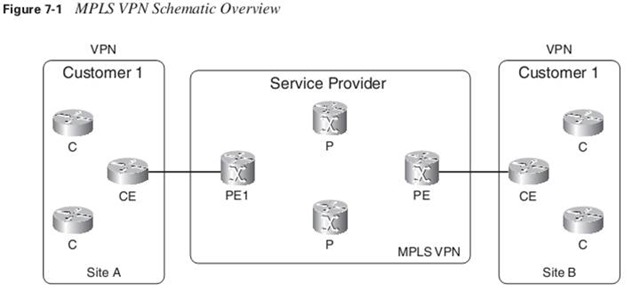
The CE router does not peer with any of the CE routers from the other sites across the service provider network, as with the overlay model. The name  peer-to-peer model  is derived from the fact that the CE and PE form a peer at Layer 3.

Virtual routing/forwarding (VRF): is a VPN routing and forwarding instance. It is the name for the combination of the VPN routing table, the VRF Cisco Express Forwarding (CEF) table, and the associated IP routing protocols on the PE router.

A PE router holds the global IP routing table, but also a VRF routing table per VPN connected to the PE. Continue reading “MPLS Fundamentals: 5 – MPLS-VPN”

Share this!

GLBP Overview

In this post you’ll read some key points of GLBP and then I’ll invite you to test a sample implementation of GLBP.

GLBP means Gateway Load Balancing Protocol. What an easy definition 😀

It is a VGP (Virtual Gateway Protocol) / FHRP, similar to HSRP and VRRP. It’s one of the strongest kind of VGPs because it is capable of using multiple physical gateways at the same time.

This protocol attempts to overcome the limitations of existing redundant router protocols by adding basic load balancing functionality.

In addition to being able to set priorities on different gateway routers, GLBP allows a weighting parameter to be set. Based on this weighting (compared to others in the same virtual router group), ARP requests will be answered with MAC addresses pointing to different routers. Thus, load balancing is not based on traffic load, but rather on the number of hosts that will use each gateway router. By default GLBP load-balances in round-robin fashion.

GLBP elects one AVG (Active Virtual Gateway) for each group. Other group members act as backup in case of AVG failure. In case there are more than two members, the second best AVG is placed in the Standby state and all other members are placed in the Listening state. This is monitored using hello and holdtime timers, which are 3 and 10 seconds by default. The elected AVG then assigns a virtual MAC address for each member of the GLBP group, including itself, thus enabling AVFs (Active Virtual Forwarders). Each AVF assumes responsibility for forwarding packets sent to its virtual MAC address. There could be up to four active AVFs at the same time.

Continue reading “GLBP Overview”

Share this!